Recordable optical storage systems

A technology of optical and storage media, applied in the field of optical storage systems, can solve problems such as incompleteness, OPC failure, and long-term testing

Inactive Publication Date: 2007-12-12
KONINKLIJKE PHILIPS ELECTRONICS NV
View PDF0 Cites 1 Cited by
  • Summary
  • Abstract
  • Description
  • Claims
  • Application Information

AI Technical Summary

Problems solved by technology

But that information may not always be correct and can cause OPC failures
[0010] Another disadvantage of currently used runout / sigma (σ) OPC procedures is that a large number of panels are required in order to average variations along the circumference of the disk (e.g. eccentricity)
The large area required reduces the available data storage space and also takes a long time to test

Method used


Image

  • Recordable optical storage systems
  • Recordable optical storage systems
  • Recordable optical storage systems

Examples


Embodiment Construction

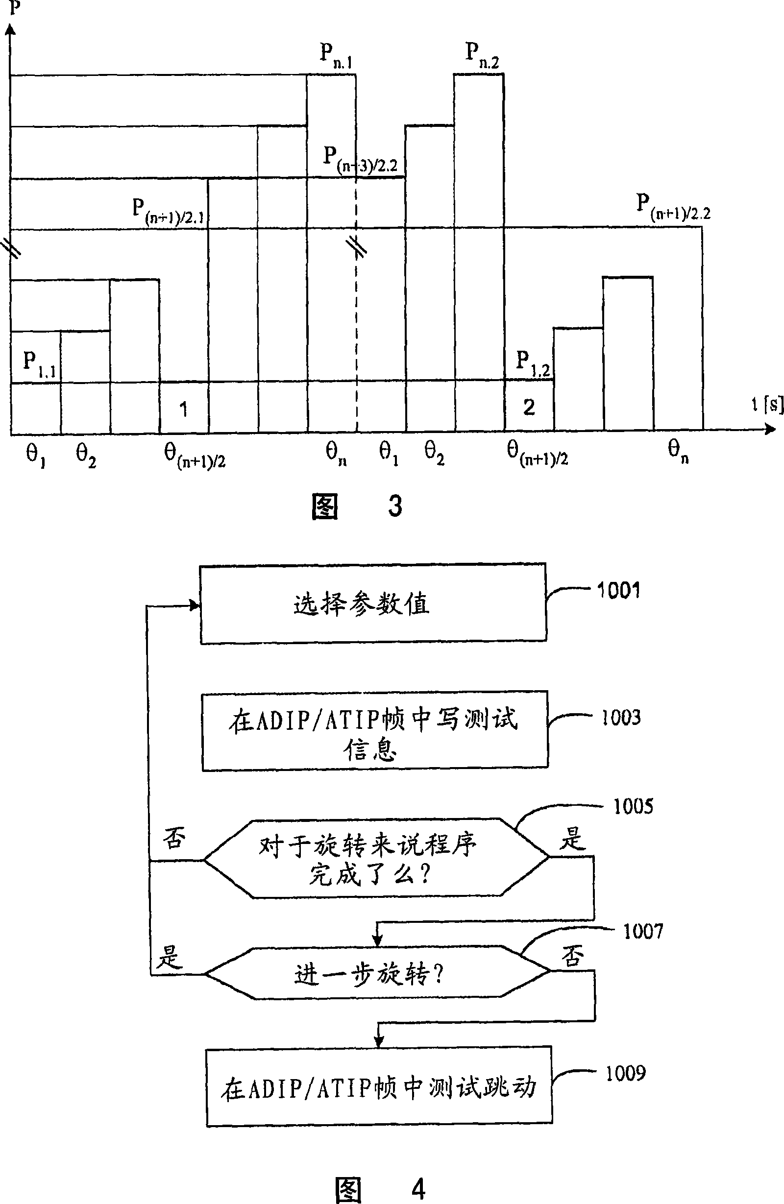
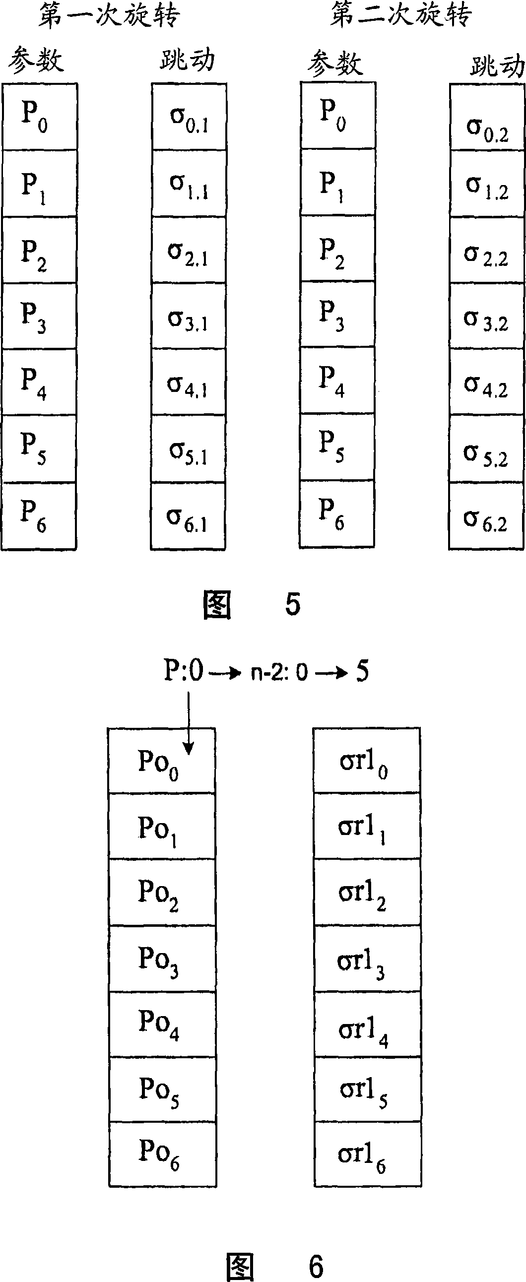
[0040] The sigma-OPC program of the present invention is executed using the test area of ​​the disc. In order to provide fast and space-saving OPC, embodiments of the present invention utilize only two rotations of the disk to provide the sigma-OPC procedure.

[0041] Although the invention is primarily described with reference to CD-R(W) and DVD-R(W) discs, it should be understood that the invention is applicable to applications requiring optimal parameters for writing information to or reading information from the medium. any optical recording medium. For example, the present invention is also applicable to, but not limited to, DVD-R_DL, DVD-RW_DL, Blu-ray Disc, and the like.

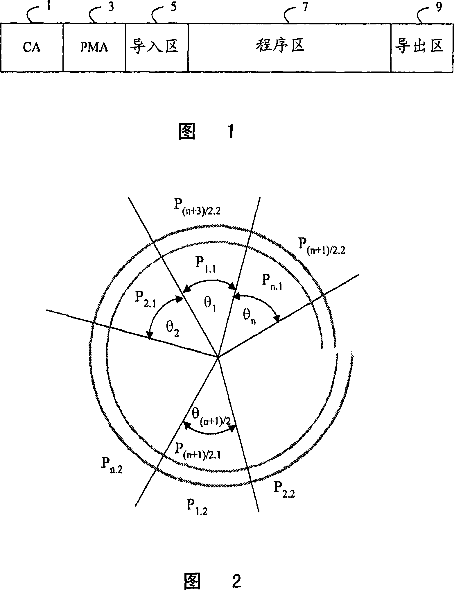
[0042] Figure 1 shows a side view of a standard CD-RW disc. The "Calibration Area" (CA) 1 defines the test area of ​​the disc, in which area of ​​the disc any OPC procedure normally takes place. A program memory area (PMA) 3, lead-in and lead-out areas 5, 9 and a program area 7 are provided on the ...


PUM


Abstract

A last optimum parameter value control method is disclosed, with a laser parameter value being adjusted in a predetermined sequence at an ADIP / ATIP frame of an optical recording medium. Jitter is measured at each ADIP / ATIP frame in order to obtain an average jitter value for that particular frame, and hence parameter value.

Description

field of invention [0001] The present invention relates generally to recordable optical storage systems, and more particularly to determining optimum read and write parameters for use with recordable optical storage systems and optical storage discs. Background technique [0002] As is well known, CD-R (Compact Disc Recordable) discs and the like are constructed of optical stacks. The stackup typically consists of a polycarbonate substrate, a photosensitive dye layer, a gold or silver alloy reflector, and a protective lacquer layer. Data is written to the disc by focusing a high power laser onto the dyed layer to heat an area thereby changing the reflectivity of the area. These regions form a helical track of variable length marks (low reflective regions) and lands (non-recessed portions) (high reflective regions between the marks). The resulting pattern of marks and lands encodes the data stored on the disc. Each transition between the marked area and land corresponds to...

Claims


Application Information

Patent Timeline
Patent Type & Authority Applications(China)
IPC IPC(8): G11B7/125
CPCG11B7/1267G11B7/0956G11B7/126
Inventor T·P·范恩德特
Owner KONINKLIJKE PHILIPS ELECTRONICS NV
Why Eureka
Try Eureka