Methods and systems for improving transmission shifting

a transmission shifting and transmission technology, applied in mechanical equipment, instruments, transportation and packaging, etc., can solve the problems of difficult to get the prime mover to decelerate at a desired rate, and the transmission output torque may increase more than is desired, so as to reduce the disturbance of the torque, reduce the increase of the torque, and reduce the effect of the disturban

Inactive Publication Date: 2013-11-07
FORD GLOBAL TECH LLC
View PDF6 Cites 35 Cited by
  • Summary
  • Abstract
  • Description
  • Claims
  • Application Information

AI Technical Summary

Benefits of technology

[0003]A transmission may upshift from a lower gear to a higher gear to allow a prime mover (e.g., an engine or an electric machine) to operate at an efficient operating speed while a vehicle in which the prime mover and the transmission reside continues to accelerate. During an upshift, the prime mover may be decelerated to reduce a torque increase that may occur at the end of the upshift at the transmission output shaft. However, it may be difficult to get the prime mover to decelerate at a desired rate and reduce a torque disturbance at the transmission output shaft since the prime mover is accelerating just before the shift begins. Consequently, the transmission output torque may increase more than is desired as a result of an upshift.
[0005]By coupling an engine to a transmission in response to a request to upshift the transmission, torque at the transmission input shaft may be reduced so as to reduce transmission output shaft torque after the shift. In particular, a driveline disconnect clutch may close in response to a transmission shift, thereby reducing torque at the transmission input shaft. A portion of torque applied to the transmission input shaft can be used to rotate the engine so that the transmission output shaft torque may be reduced. Additionally, after the shift is complete or during the torque phase of the shift, engine torque may be provide to the driveline so that vehicle acceleration may be maintained.
[0006]The present description may provide several advantages. In particular, the approach may reduce driveline torque disturbances during upshifting. Additionally, the approach may allow engine torque to be available to the driveline after the shift.

Problems solved by technology

However, it may be difficult to get the prime mover to decelerate at a desired rate and reduce a torque disturbance at the transmission output shaft since the prime mover is accelerating just before the shift begins.
Consequently, the transmission output torque may increase more than is desired as a result of an upshift.

Method used


Image

  • Methods and systems for improving transmission shifting
  • Methods and systems for improving transmission shifting
  • Methods and systems for improving transmission shifting

Examples


Embodiment Construction

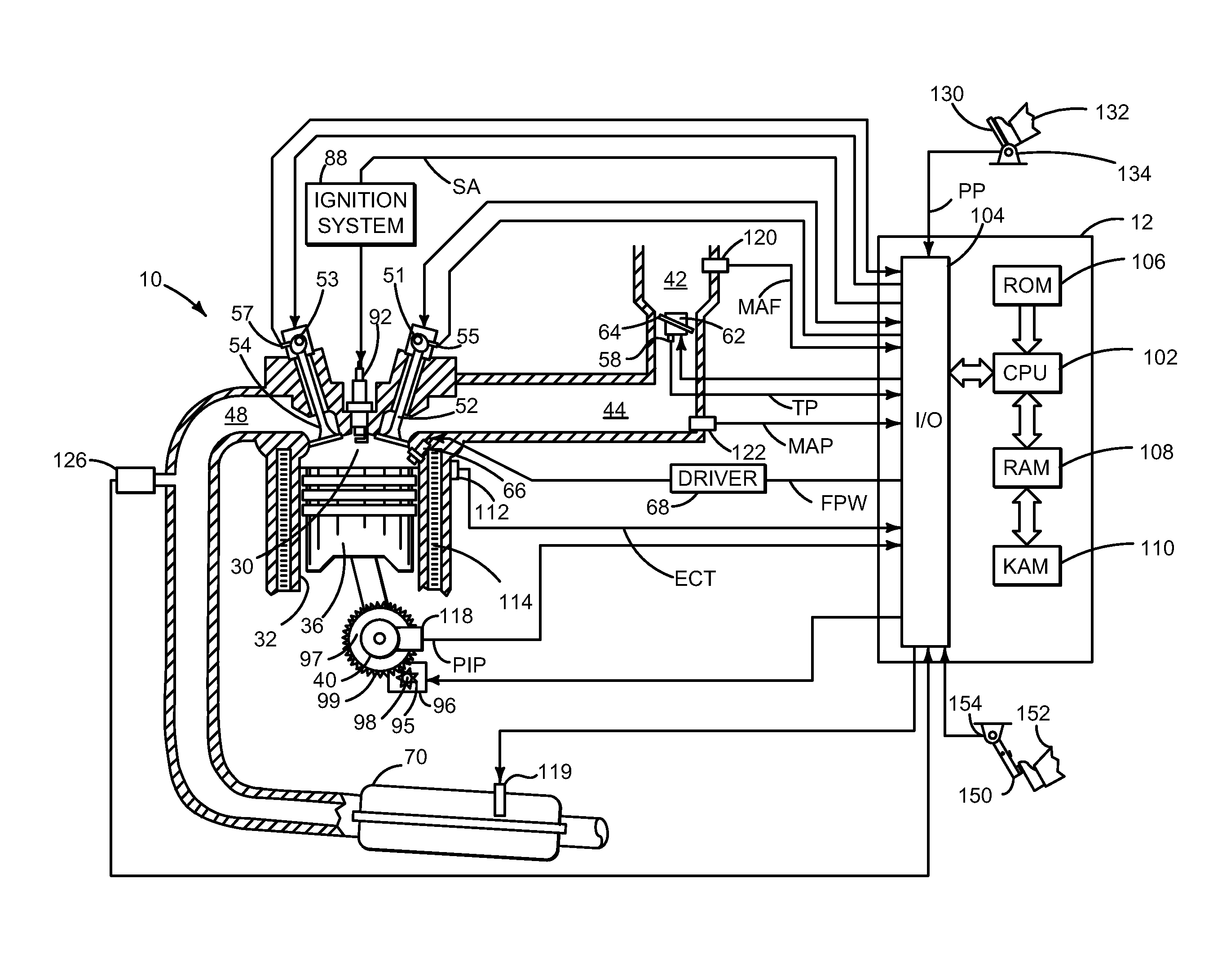
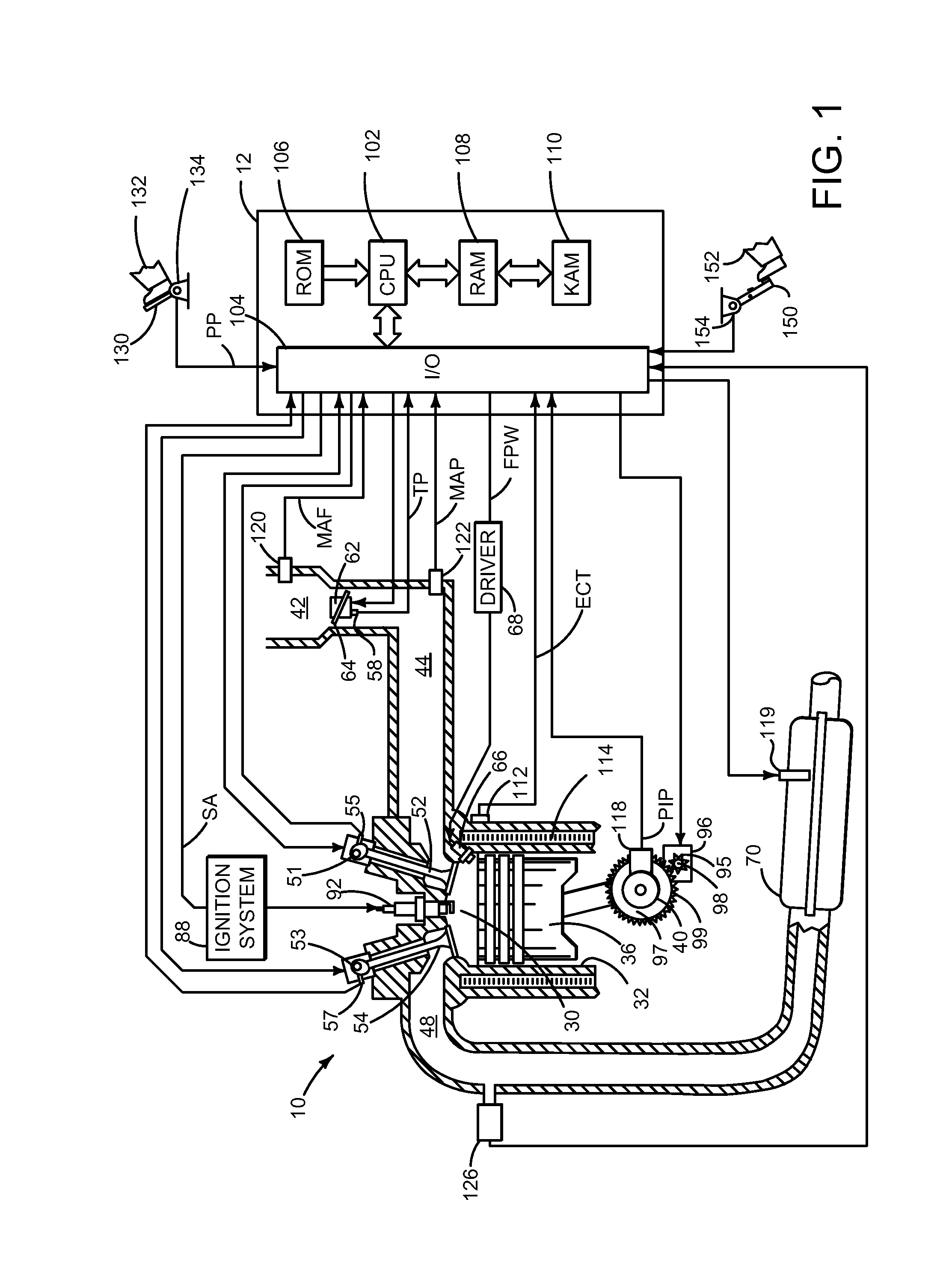
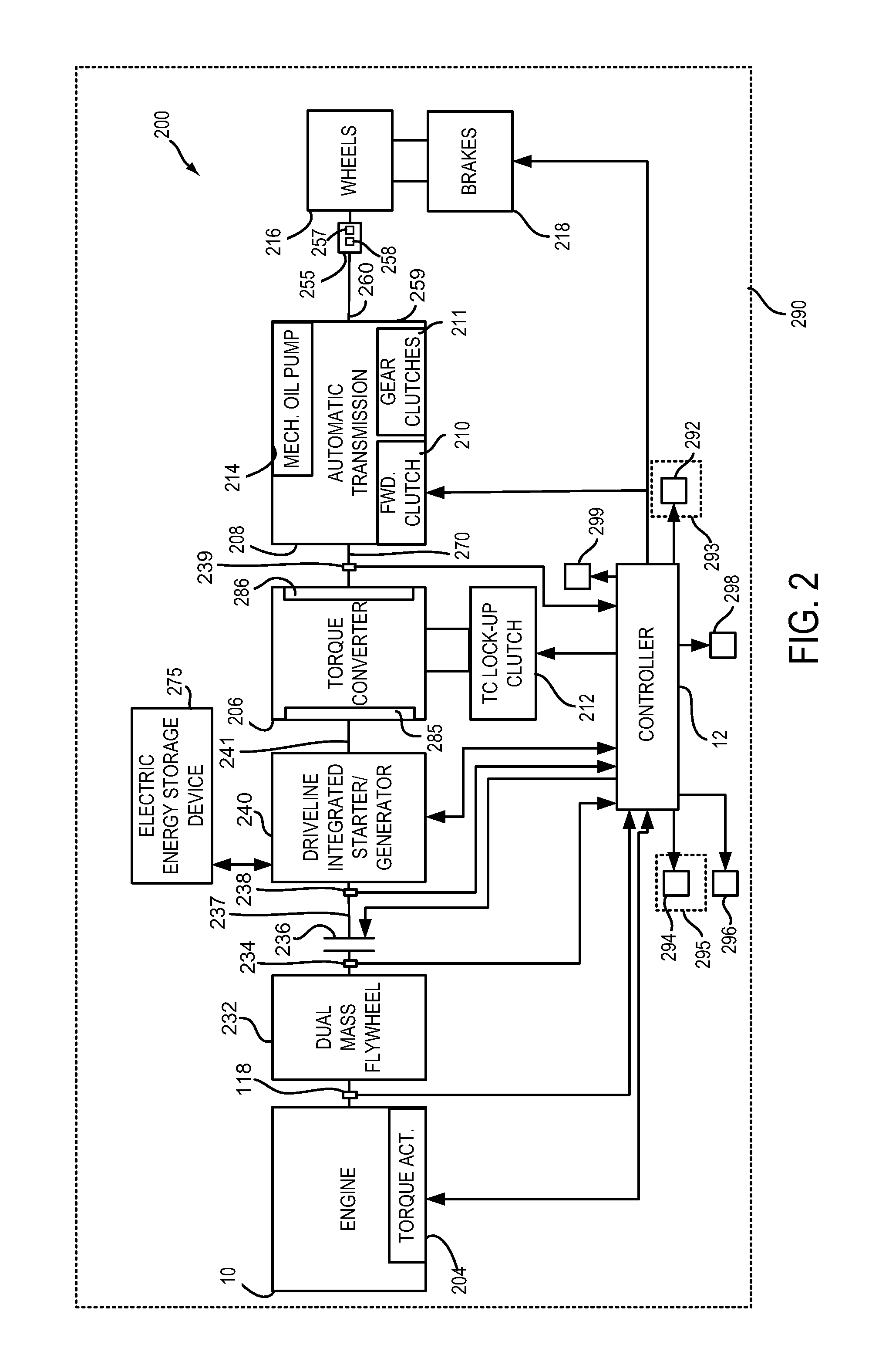
[0026]The present description is related to controlling a driveline of a hybrid vehicle. The hybrid vehicle may include an engine and electric machine as shown in FIGS. 1-3. The engine may be operated with or without a driveline integrated starter / generator (e.g., an electric machine or motor that may be abbreviated DISG) during vehicle operation. The driveline integrated starter / generator is integrated into the driveline on the same axis as the engine crankshaft and rotates whenever the torque converter impeller rotates. Further, the DISG may not be selectively engaged or disengaged with the driveline. Rather, the DISG is an integral part of the driveline. Further still, the DISG may be operated with or without operating the engine. The mass and inertia of the DISG remain with the driveline when the DISG is not operating to provide or absorb torque from the driveline.

[0027]The driveline may be operated according to the method of FIG. 4. In some examples, the driveline may be operat...


PUM


Abstract

Systems and methods for improving operation of a hybrid vehicle are presented. In one example, an engine is couple to a transmission in response to a transmission upshift to reduce transmission output shaft torque disturbances.

Description

CROSS REFERENCE TO RELATED APPLICATIONS[0001]The present application claims priority to U.S. of America Provisional Patent Application 61 / 643,139 filed on May 4, 2012, the entire contents of which are hereby incorporated by reference for all purposes.FIELD[0002]The present description relates to a system and methods for improving drivability and fuel economy of a vehicle. The methods may be particularly useful for engines that are selectively coupled to an electrical machine and a transmission.BACKGROUND AND SUMMARY[0003]A transmission may upshift from a lower gear to a higher gear to allow a prime mover (e.g., an engine or an electric machine) to operate at an efficient operating speed while a vehicle in which the prime mover and the transmission reside continues to accelerate. During an upshift, the prime mover may be decelerated to reduce a torque increase that may occur at the end of the upshift at the transmission output shaft. However, it may be difficult to get the prime move...

Claims


Application Information

Patent Timeline
Patent Type & Authority Applications(United States)
IPC IPC(8): B60W10/02B60W10/10
CPCB60W10/023B60W10/10B60K6/48B60W10/02B60W20/40Y10S903/902B60W2510/083B60W2510/0275Y02T10/62Y10S903/93B60W20/14B60W10/06B60K2006/4825B60W10/30B60W10/08B60W30/20B60W2030/203
Inventor PIETRON, GREGORY MICHAELDOERING, JEFFREY ALLENREED, DENNIS CRAIGGIBSON, ALEX O'CONNORLEE, SEUNG-HOON
Owner FORD GLOBAL TECH LLC
Why Eureka
Try Eureka