Impinging stream reactor

An impinging flow reactor and reactor technology, applied in the field of reactors, can solve the problems of only focusing on opposing collisions, weak mixing, and difficulty in contacting fluid masses with each other, and achieve the effects of increasing turbulent intensity, strengthening mixing, and strengthening the impact process.

Inactive Publication Date: 2013-03-27
湖北恒信石化设备有限公司
View PDF7 Cites 34 Cited by
  • Summary
  • Abstract
  • Description
  • Claims
  • Application Information

AI Technical Summary

Problems solved by technology

However, in many impingement flow reactor patents, such as the patent "An impingement flow reactor for liquid phase reaction" (patent number: CN200510045866.5), through the action of the pump, the liquid is given a certain speed to make it collide with each other. Another patent "Non-rotating vertical circulation impingement flow reactor" (Patent No.: CN200720083472.3) promotes the fluid to collide with each other through the action of the propeller in the guide tube, both of which can achieve the purpose of enhanced mixing, but due to the total flow It tends to move with streamlines, and it is difficult for the divided flow groups to contact each other. The above-mentioned patents only focus on the collision of two fluids. In addition, they rarely involve the movement of the fluid groups and the impact area. Therefore, the enhanced mixing in the impact area has a certain limit, and in addition to the enhanced mixing in the impact area, the mixing in other areas is weak

Method used


Image

  • Impinging stream reactor
  • Impinging stream reactor
  • Impinging stream reactor

Examples


Embodiment 1

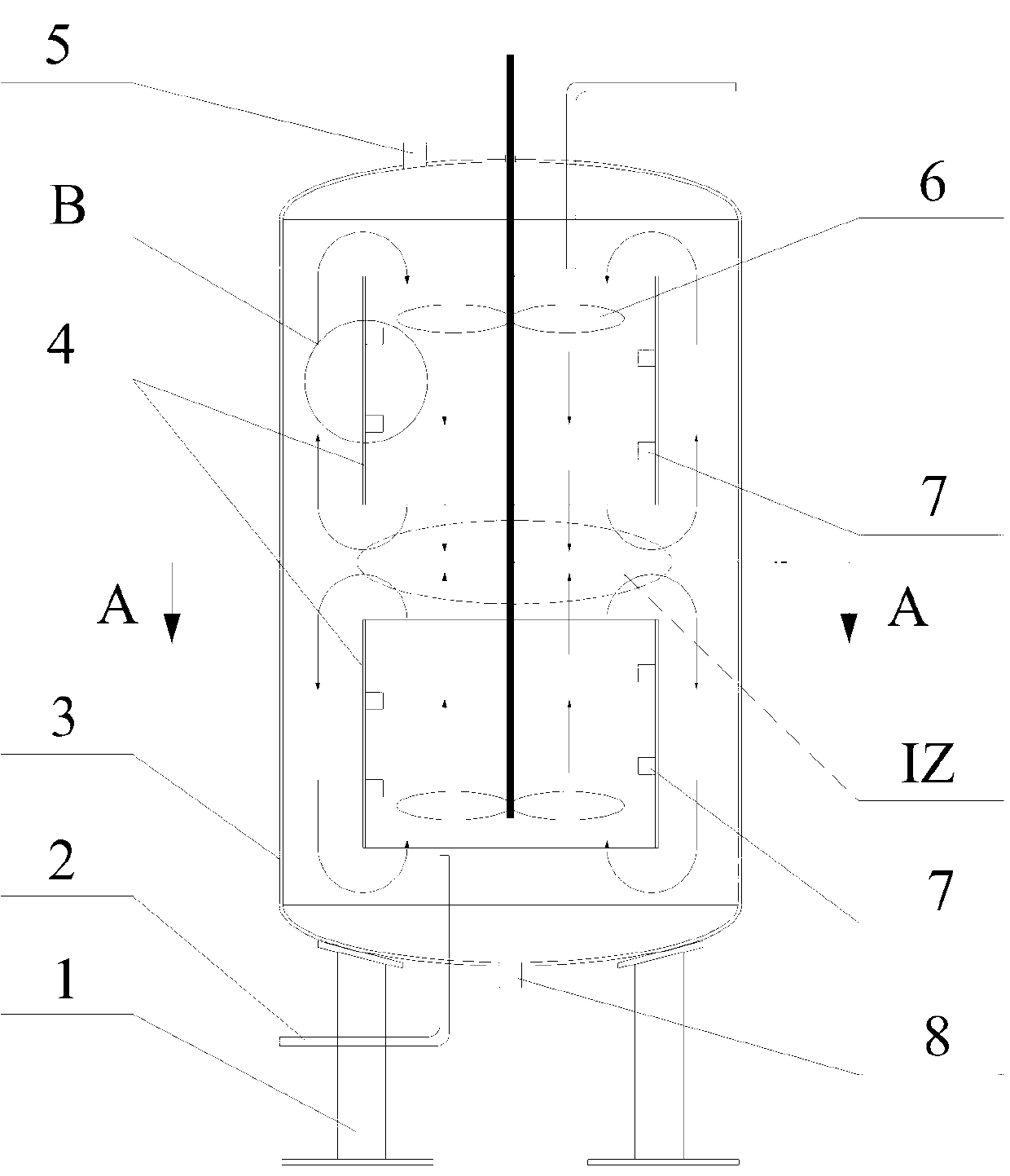
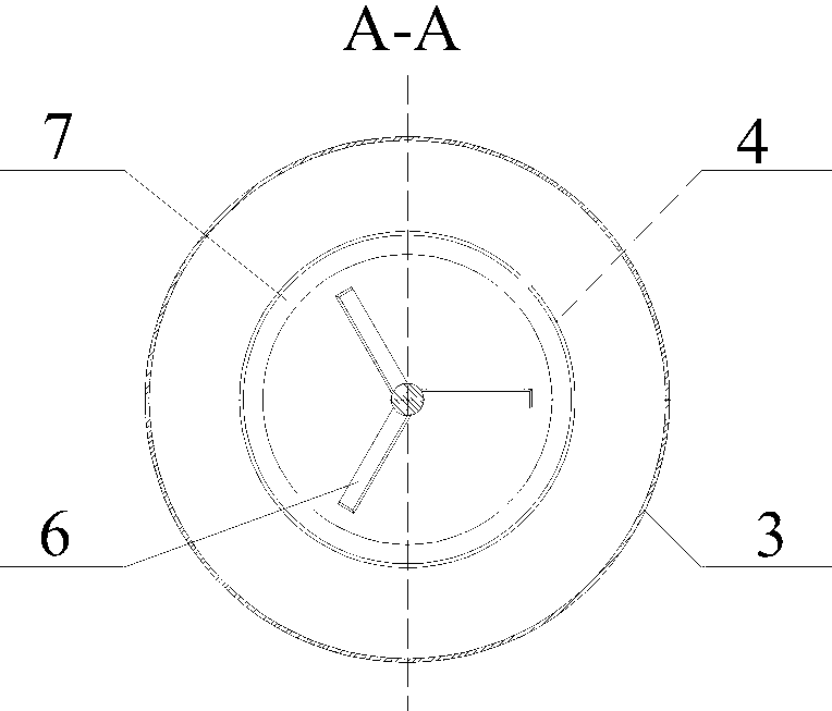
[0028] like Figure 1 to Figure 8 Shown, a kind of impinging flow reactor, it is vertical structure, and it comprises reactor support 1, cylindrical reactor 3, feed pipe 2, exhaust pipe 5, unloading pipe 8, guide tube 4 , spiral deflector 7 and propeller 6, the reactor 3 is fixed on the reactor support 1, the upper and lower ends of the reactor 1 are provided with a feed inlet, connected by the feed pipe 2, the discharge pipe 8 Installed at the lower end of the reactor 1, the exhaust pipe 5 is arranged at the upper end of the reactor 3, and two guide tubes 4 are coaxially installed at the upper and lower ends of the inside of the reactor 3, and at the top of the guide tube A fluid impact zone IZ is formed between the outlets, and two propellers 6 with opposite rotations are coaxially arranged in the guide tube 4, which are respectively used to push the fluid from the upper end and the lower end to flow to the fluid impact zone IZ through the guide tube 4, in order to To stren...

Embodiment 2

[0035] like Figure 9 , 10 As shown, the impingement flow reactor described in embodiment 2 has basically the same structure as the impingement flow reactor in embodiment 1, the difference is that it is a horizontal structure, and the feed pipe 2 is arranged at the reaction The left and right ends of the reactor 3, and the draft tube 4 is arranged at the left and right ends of the reactor 3.

[0036] In summary, the impingement flow reactor of the present invention not only retains strong microscopic mixing and continuous liquid circulation, but also strengthens the impact process and mixing outside the impact area, shortening the time for the fluid in the reactor to achieve uniform mixing , greatly improve production efficiency, and can obtain good economic performance.


PUM


Abstract

The invention discloses an impinging stream reactor. The impinging stream reactor is provided with a material inlet and a material outlet; two guide cylinders are arranged inside the reactor; a fluid impinging area is formed between the outlets of the guide cylinders; each guide cylinder is internally provided with propellers correspondingly; the spiral directions of the propellers are opposite; and the propellers are respectively used for pushing fluid to flow from the material inlet to the impinging area through the guide cylinders. The impinging stream reactor is characterized in that the inner wall of each guide cylinder is provided with spiral type guide blades. Strong micromixing and continuous circulation flow of liquid are maintained, mixing during impinging and outside the impinging area is strengthened, the time for the fluid inside the reactor to achieve uniform mixing is shortened, the production efficiency is enhanced remarkably and good economic performance can be obtained.

Description

technical field [0001] The invention relates to a reactor in the field of chemical production, in particular to an impact flow reactor. Background technique [0002] The chemical reaction process is the core and key of chemical production. For most liquid phase reaction processes, the mass transfer and mixing effect of the reactor (device) device has a great influence on the reaction quality and efficiency. Stirred Tank Reactor (STR for short) is the most widely used reactor at present, but the mixing effect of STR is not ideal for the rapid reaction process, and even adversely affects the reaction quality and efficiency in some cases. Therefore, the research and development of a new type of high-efficiency mixing reactor has become an urgent problem to be solved in the current chemical industry to strengthen the rapid reaction process, and many impingement flow reactor patents have emerged as the times require. Its main feature is to achieve enhanced transmission throu...

Claims


Application Information

Patent Timeline
Patent Type & Authority Applications(China)
IPC IPC(8): B01J19/18
Inventor 杨侠罗燕郭钊万攀
Owner 湖北恒信石化设备有限公司
Why Eureka
Try Eureka