Apparatus and method for engine braking

a technology of engine braking and apparatus, which is applied in the direction of valve arrangement, machines/engines, output power, etc., can solve the problems of obviating the danger of accidents resulting from brake failure, reducing the complexity of the system, and reducing the risk of brake failure. , the effect of fewer components

Inactive Publication Date: 2010-02-18
YANG ZHOU
View PDF21 Cites 31 Cited by
  • Summary
  • Abstract
  • Description
  • Claims
  • Application Information

AI Technical Summary

Benefits of technology

[0035]The engine braking apparatus according to the embodiments of the present invention have many advantages over the prior

Problems solved by technology

While the normal drum or disc type wheel brakes of the vehicle are capable of absorbing a large amount of energy over a short period of time, their repeated use, for example, when operating in hilly terrain, could cause brake overheating and failure.
The use of an engine brake will substantially reduce the use of the wheel brakes, minimize their wear, and obviate the danger of accidents resulting from brake failure.
This arrangement may add unnecessary height, weight, and costs to the engine.
Many of the above-noted problems result from viewing the braking system as an accessory to the engine rather than as part of the engine itself.
Another disadvantage associated with the conventional prior art CREB system is due to the fact that the load from engine braking is supported by the engine components.
Thus, the overall weight, height, and cost of using the prior art CREB system are likely to be excessive, and limit its application.
Although the engine brake system disclosed in the '116 patent has enjoyed considerable commercial success due to its high performance and compact size, it has some drawbacks.
One of the drawbacks is that the engine braking rocker arm could get away from the neutral position and contact the cam and the valve bridge during the normal engine operati

Method used


Image

  • Apparatus and method for engine braking
  • Apparatus and method for engine braking
  • Apparatus and method for engine braking

Examples


Embodiment Construction

[0043]Reference will now be made in detail to presently preferred embodiments of the invention, examples of which are illustrated in the accompanying drawings. Each example is provided by way of explanation, not limitation, of the invention. In fact, it will be apparent to those skilled in the art that modifications and variations can be made in the present invention without departing from the scope and spirit thereof. For instance, features illustrated or described as part of one embodiment may be used on another embodiment to yield a still further embodiment. Thus, it is intended that the present invention covers such modifications and variations as come within the scope of the appended claims and their equivalents.

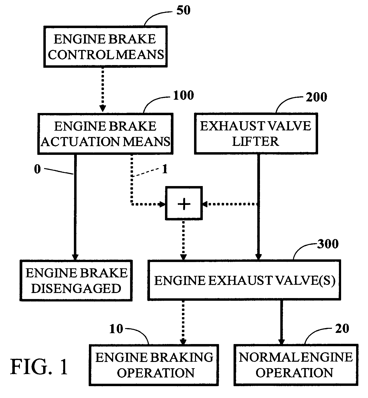
[0044]FIG. 1 is a flow chart illustrating the general relationship between a normal engine operation 20 and an added engine braking operation 10 according to one version of the present invention. An internal combustion engine contains an exhaust valve system 300 and an ...


PUM


Abstract

Apparatus and method are disclosed for converting an internal combustion engine from a normal engine operation (20) to an engine braking operation (30). The engine has an exhaust valve train containing at least one exhaust valve (300a or 300) and an exhaust valve lifter (200). The apparatus has an actuation means (100) including a dedicated load supporting system and a hydraulic system. The hydraulic system is integrated into the exhaust valve train and has a hydraulic piston (160) that can slide between an inoperative position (0) and an operative position (1). In the inoperative position (0), the hydraulic piston (160) is retracted and separated from the dedicated load supporting system, and the actuation means (100) is disengaged from the at least one exhaust valve (300a or 300). In the operative position (1), the hydraulic piston (160) is extended and engaged with the dedicated load supporting system, and the actuation means (100) opens the at least one exhaust valve (300a or 300) for the engine braking operation (30). The dedicated load supporting system includes a dedicated valve lifter (200b) for the engine braking operation (30). The dedicated load supporting system may also includes a housing (125) that is used to hold the at least one exhaust valve (300a or 300) open when the hydraulic piston (160) is at the extended or operative position (1), which is reached after the at least one exhaust valve (300a or 300) is actuated by the normal exhaust valve lifter (200). The apparatus also has a control means (50) for moving the hydraulic piston (160) between the inoperative position (0) and the operative position (1).

Description

BACKGROUND OF THE INVENTION[0001]1. Field of Invention[0002]The present invention relates generally to the braking of an internal combustion engine, specifically to engine braking apparatus and method for converting an internal combustion engine from a normal engine operation to an engine-braking operation.[0003]2. Prior Art[0004]It is well known in the art to employ an internal combustion engine as brake means by, in effect, converting the engine temporarily into a compressor. It is also well known that such conversion may be carried out by cutting off the fuel and opening the exhaust valve(s) at or near the end of the compression stroke of the engine piston. By allowing compressed gas (typically, air) to be released, energy absorbed by the engine to compress the gas during the compression stroke is not returned to the engine piston during the subsequent expansion or “power” stroke, but dissipated through the exhaust and radiator systems of the engine. The net result is an effectiv...

Claims


Application Information

Patent Timeline
IPC IPC(8): F02D13/04
CPCF02D13/04F01L13/08F01L13/06F01L13/0047
Inventor YANG, ZHOU
Owner YANG ZHOU
Why Eureka
Try Eureka