Grinding and polishing machine for grinding and/or polishing workpieces in optical quality

一种光学质量、抛光机的技术,应用在磨削/抛光设备、磨削/抛光安全装置、光学平面磨床等方向,能够解决总成本高、大结构空间需求等问题,达到避免不正确测量的效果

Active Publication Date: 2007-12-19
SATISLOH AG
View PDF3 Cites 17 Cited by
  • Summary
  • Abstract
  • Description
  • Claims
  • Application Information

AI Technical Summary

Problems solved by technology

The number of spindles, the complexity of the spindle control system, the initial outlay, the subsequent adjustments and the greater installation space requirements make the overall costs considerably high

Method used


Image

  • Grinding and polishing machine for grinding and/or polishing workpieces in optical quality
  • Grinding and polishing machine for grinding and/or polishing workpieces in optical quality
  • Grinding and polishing machine for grinding and/or polishing workpieces in optical quality

Examples


Embodiment Construction

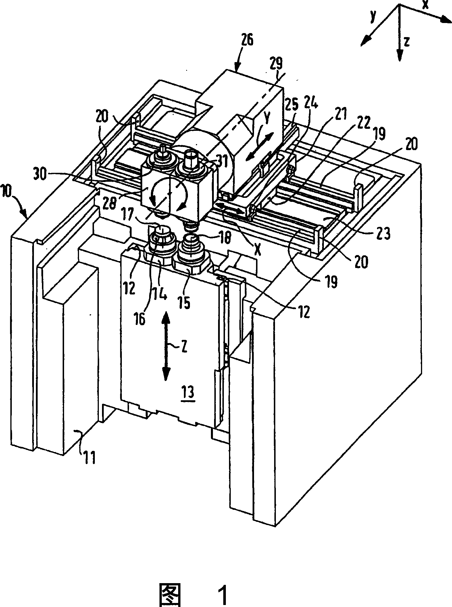
[0030] 1 shows a CNC-controlled grinding and polishing machine 10, in particular for machining optical lenses, in a Cartesian coordinate system in which the letter x designates the width direction of the machine 10 and the letter y denotes the longitudinal direction of the machine 10 , and the letter z denotes the heightwise direction of the machine 10 .

[0031]The machine 10 has a frame 11 formed from a single block of polymer concrete. Two guide rails 12 are fastened to the machine frame 11 at the front of the machine, which extend parallel to each other in the vertical height direction z. A Z-shuttle 13 movable in a CNC-controlled manner in both directions of the Z-axis by means of associated CNC drives and control elements (not shown) is mounted on the guide rail 12 so that it can be moved via Guide the carriage to shift.

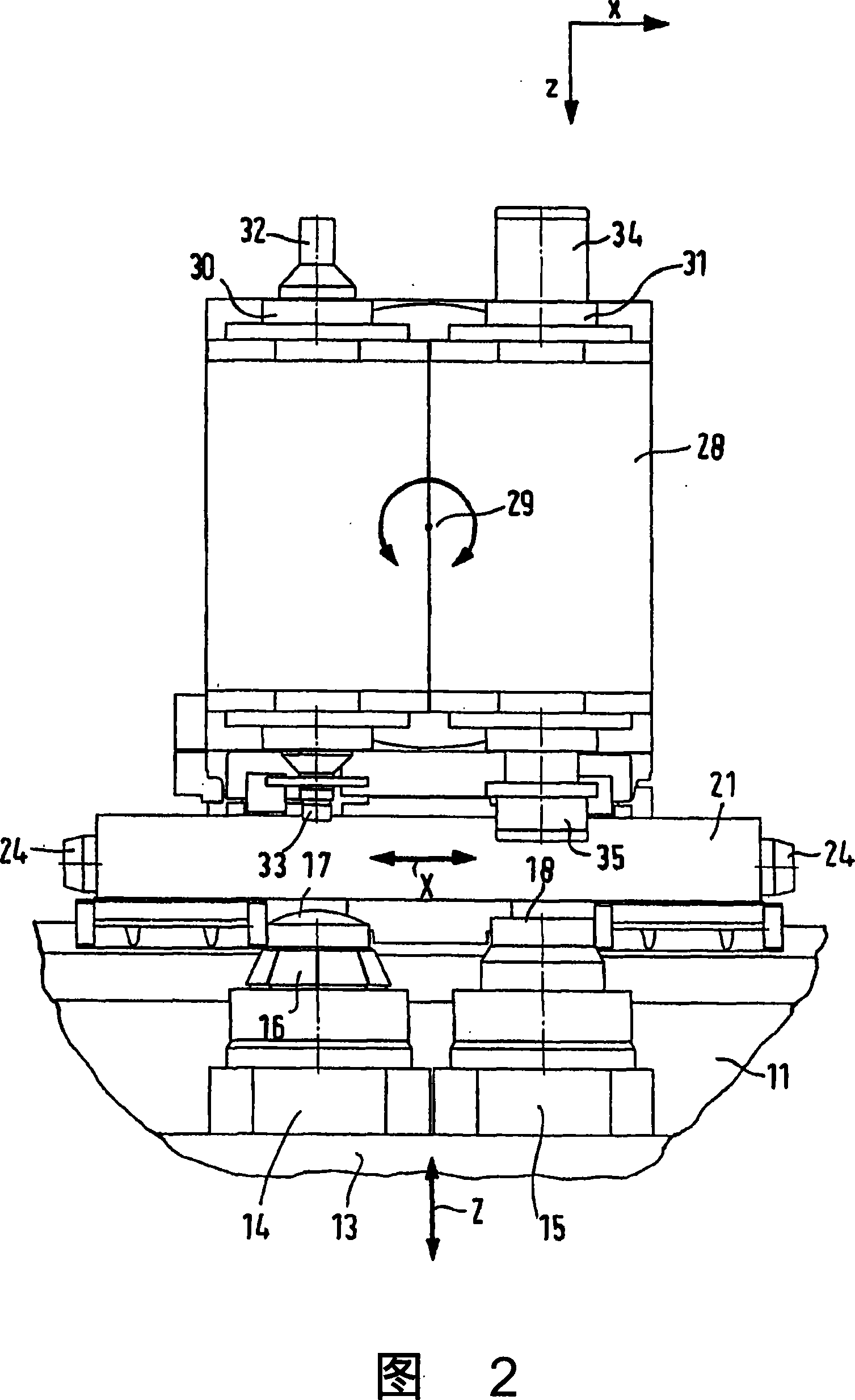
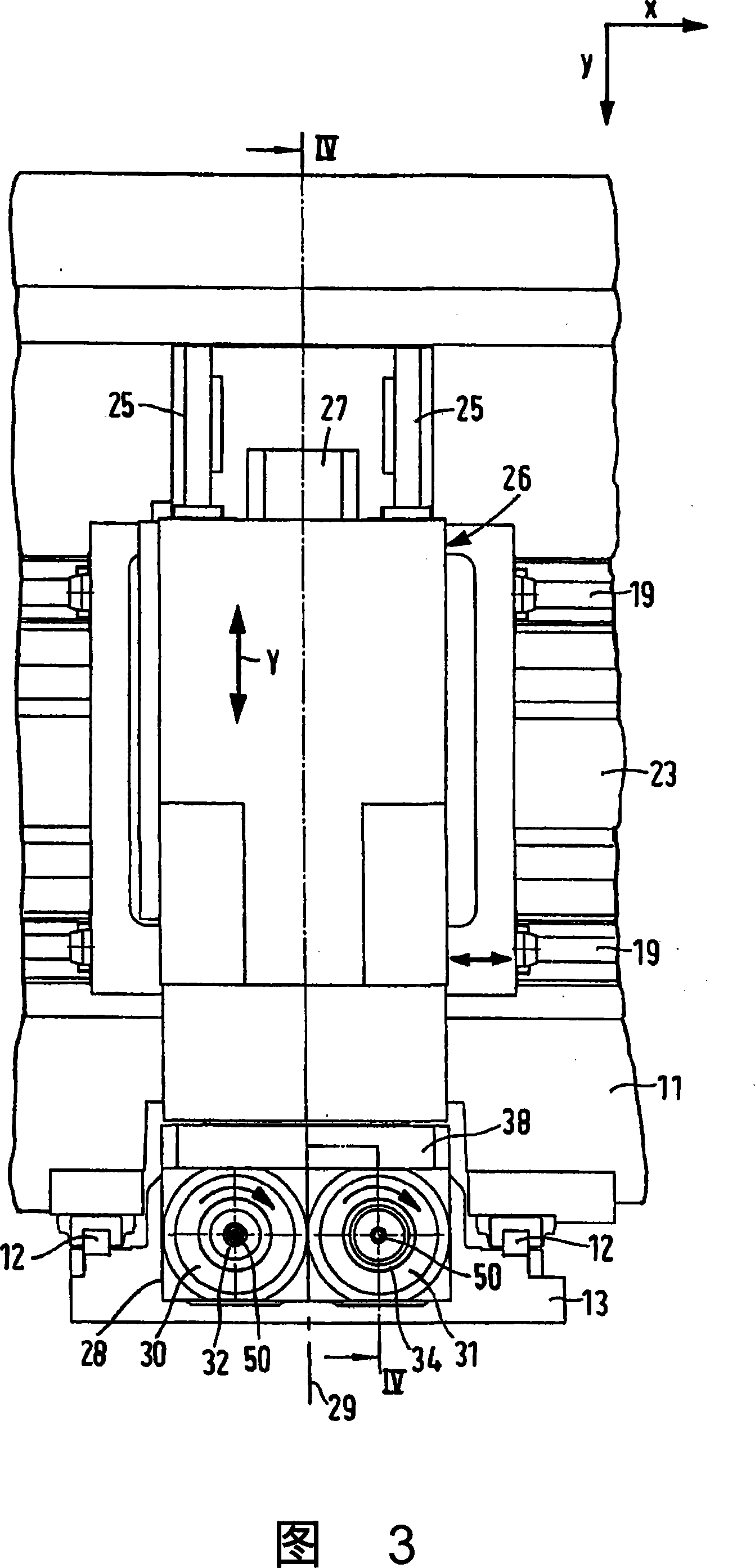
[0032] On the Z-shuttle 13 there are two workpiece spindles 14 and 15 which are arranged parallel to each other and whose angular position relative ...


PUM


Abstract

A grinding and polishing machine, in particular for lenses, has at least one tool spindle and at least one workpiece spindle which are adjustable relative to each other in the vertical direction relative to each other. The tool spindle is constructed to hold a respective tool on the same axis at both ends thereof and is mounted in a spindle housing which can be pivoted about a pivot axis arranged at right angles to the tool spindle in order to provide in each case one tool for machining engagement and also at various defined angle positions with respect to the workpiece spindle. The machine also comprises a drive device arranged on the pivotal axis and pivotably moves the tool spindle around the pivot axis for the desired machining engagement and rotates around the pivot axis to the defined angle position with respect to the workpiece spindle, thereby a compact machine with high precision is provided, which utilizes a plurality of grinding and polishing tools in a simple and economic mode.

Description

technical field [0001] The present invention relates to grinding and polishing machines for grinding and / or polishing workpieces, in particular lenses, to optical quality. In addition to machining, it should also be possible to use the machine to machine complex optics and shaped inserts. Background technique [0002] In order to realize complex machining operations, it has hitherto been necessary to use one or even several grinding and polishing machines with several precisely operating tools. In addition to single-spindle machines, machines are known that use a number of machining spindles and tool changers that can be used to automatically change the machining tools. [0003] In a known machine for machining optical workpieces (DE10029967A1), the workpiece spindles are arranged in a yoke, while the two spindles are arranged in an entry structure above the yoke according to the so-called gantry concept, which is provided with Three may be linear axes displaced perpendicu...

Claims


Application Information

Patent Timeline
Patent Type & Authority Applications(China)
IPC IPC(8): B24B13/00B24B47/22B24B13/005B24B55/02
CPCB24B13/0037B24B13/005
Inventor H·谢弗J·迪尔L·厄本
Owner SATISLOH AG
Why Eureka
Try Eureka