
3D measuring method based on two-dimensional code

A technology of three-dimensional topography and measurement method, which can be used in measurement devices, instruments, optical devices, etc., and can solve the problems of low coding efficiency, low coding accuracy, and inability to realize image coding.

Inactive Publication Date: 2007-12-19
HUAZHONG UNIV OF SCI & TECH
View PDF0 Cites 36 Cited by
  • Summary
  • Abstract
  • Description
  • Claims
  • Application Information

AI Technical Summary

Problems solved by technology

At present, the commonly used Gray coding method only realizes one-dimensional image information coding, but cannot realize two-dimensional image coding, and the coding efficiency is not high, which makes the coding accuracy of the whole measurement system not high.

Method used


Image

  • 3D measuring method based on two-dimensional code
  • 3D measuring method based on two-dimensional code
  • 3D measuring method based on two-dimensional code

Examples


Embodiment Construction

[0027] The present invention will be described in further detail below in conjunction with the accompanying drawings.

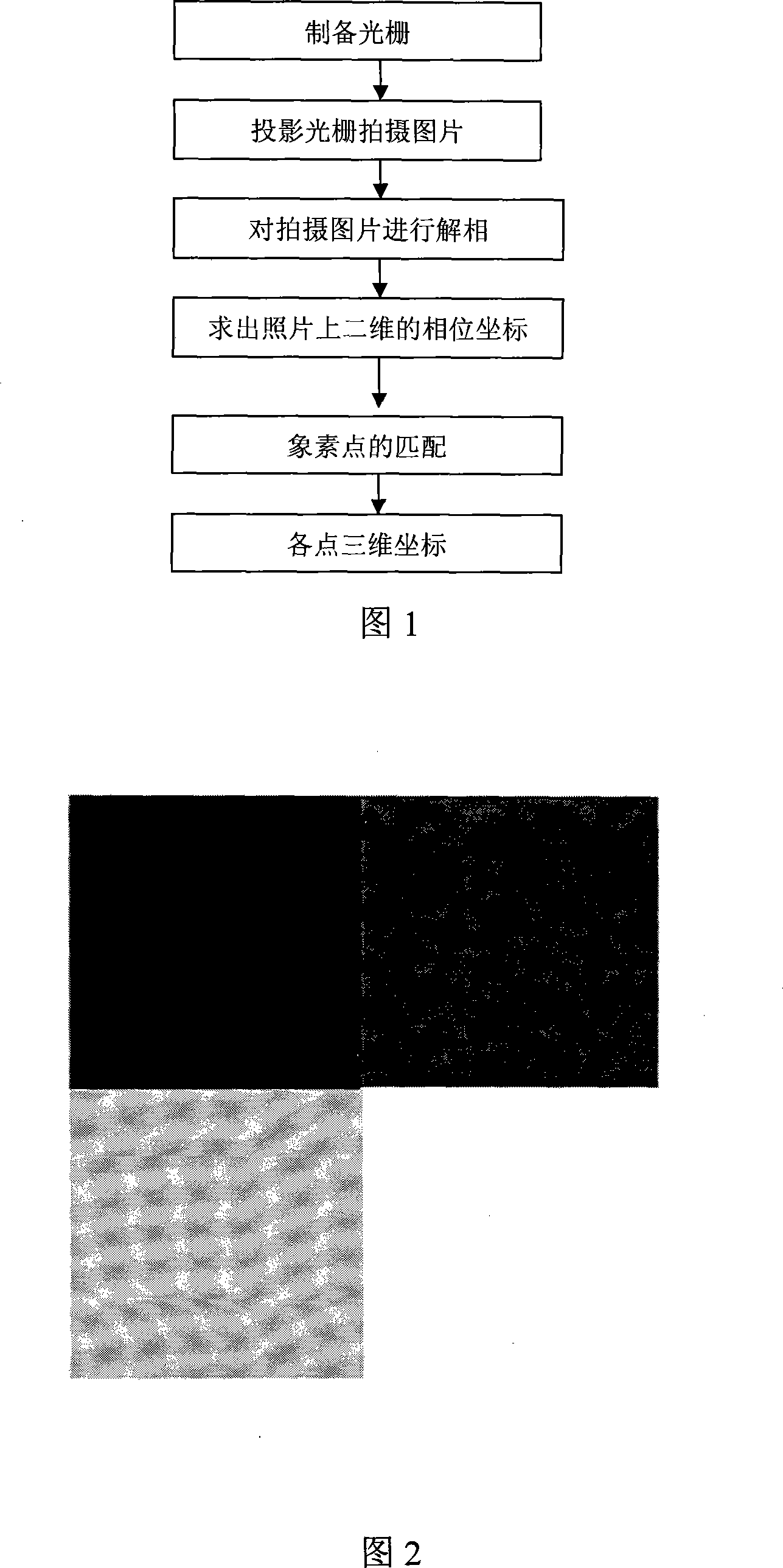
[0028] As shown in Figure 1, the step of the inventive method comprises:

[0029] (1) Prepare the grating, the requirements of the grating are:

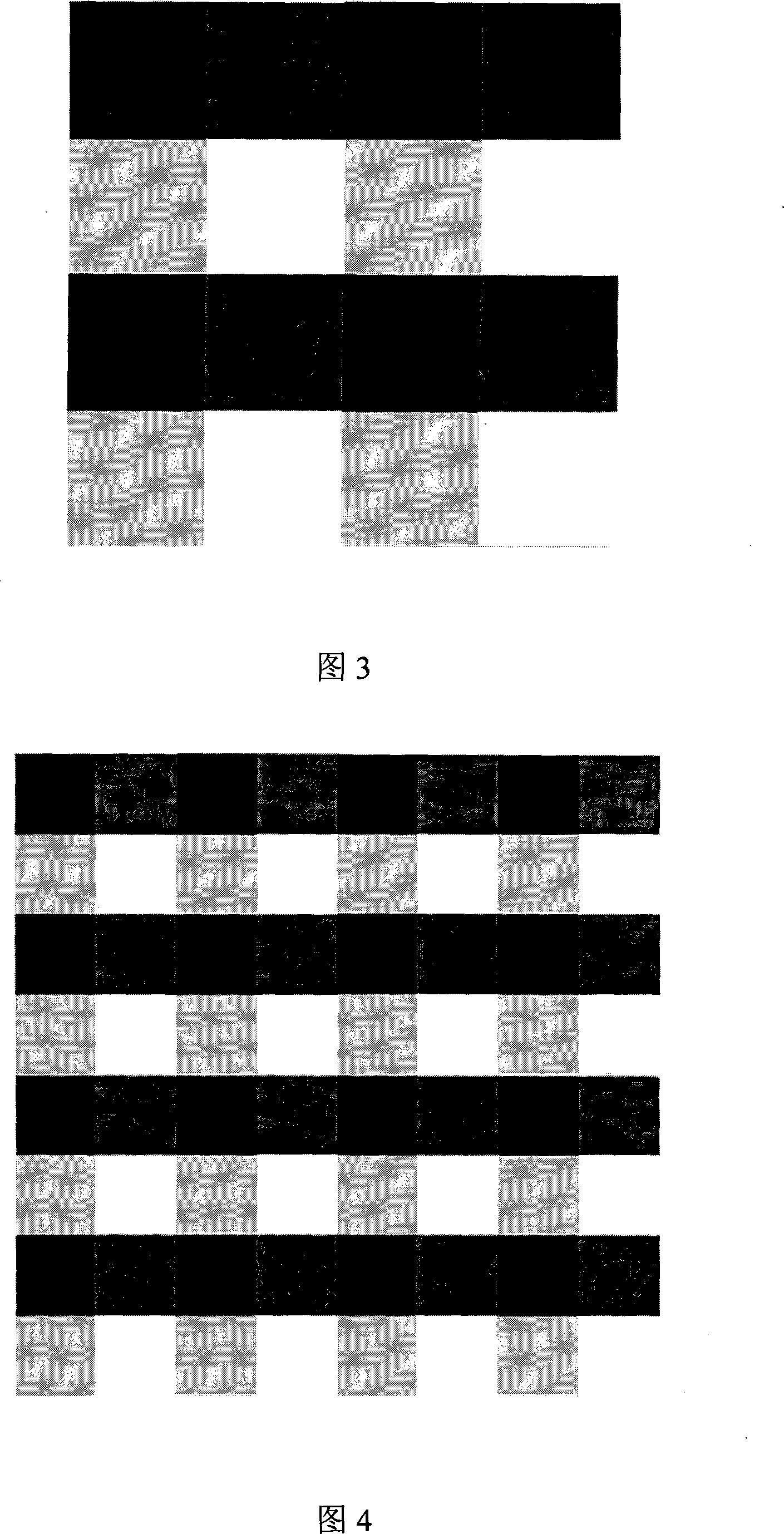
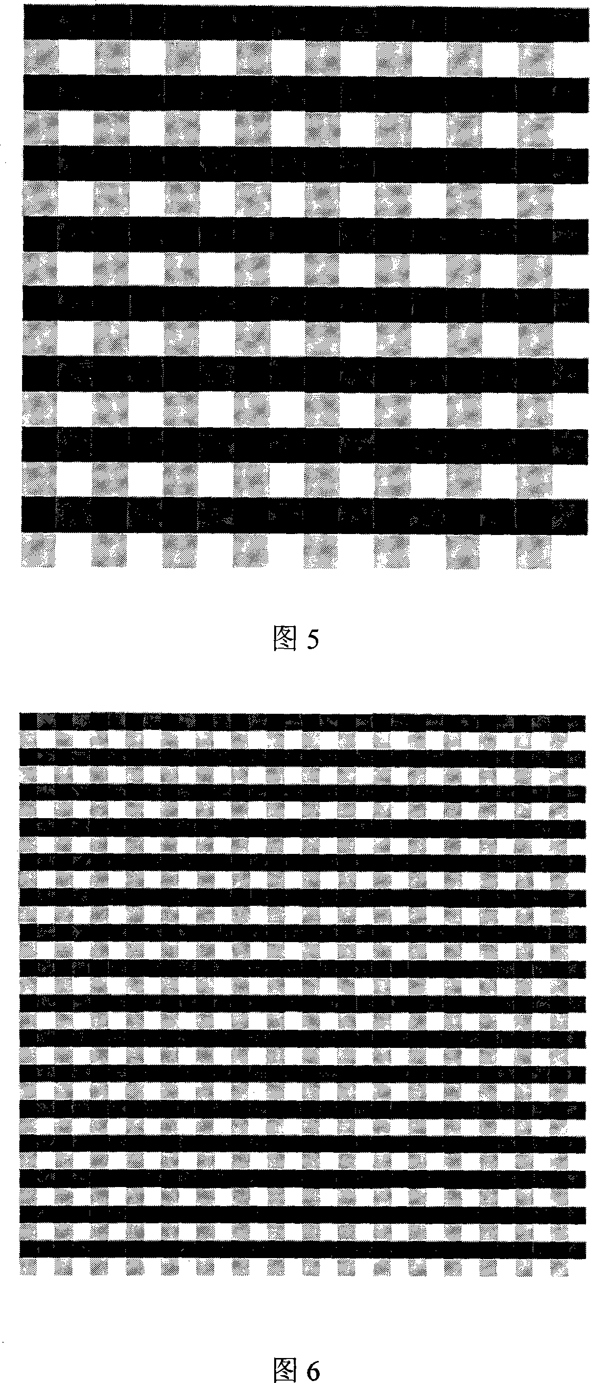
[0030] The grating is divided into checkerboard grids. The first grating is divided into four squares, the second is sixteen, and the third is four. 3 squares, the Nth is 4 N squares, and N is the number of gratings. The number of gratings can be selected according to needs, and six gratings are selected here. X and Y are the horizontal direction and the vertical direction of the grid respectively, and two grayscale pixels are set between 0-255, and the selected two grayscale levels are set as: 0, 1. The X direction is 0, 1; the Y direction is also 0, 1. We superimpose these two gray levels in the X direction and Y direction of the grid. Here we write each square in the form of (m, n), where m and n represent b...


PUM


Abstract

A 3-D morphology measuring method based on 3-D coding includes preparing N pieces of gratings, dividing said grating by check in chessboard form, projecting said grating and shooting picture then decoding said picture for obtaining actual 3-D coordinate vector of each check and carrying out stereo-matching on said 3-D coordinate vector for obtaining measurement space information.

Description

technical field [0001] The invention belongs to the field of reverse engineering measurement, in particular to a three-dimensional shape measurement method based on two-dimensional coding. Background technique [0002] The binocular grating projection structured light measurement method is a relatively advanced measurement method at present. It combines the structured light method and the stereo vision method. The projected light beam is projected on the surface of the object through the grating to form structured light. The light is coded into fringe patterns. These deformed fringes are recorded by two CCD cameras at a certain angle to the center of the projector. Each spatial point in the measurement space is encoded according to a series of projected gratings recorded. After decoding and phase calculation, each spatial point is obtained. The encoded information and phase information of a spatial point can be used to determine its spatial position and obtain measurement sp...

Claims


Application Information

Patent Timeline
Patent Type & Authority Applications(China)
IPC IPC(8): G01B11/25G01B11/03
Inventor 周钢王从军李中伟杜俊贤朱本璋李晓宁张贵姣
Owner HUAZHONG UNIV OF SCI & TECH
Learn More