Apparatus for controller-integrated motor
A technology that integrates motor and controller
- Summary
- Abstract
- Description
- Claims
- Application Information
AI Technical Summary
Problems solved by technology
Method used
Image
Examples
no. 1 approach
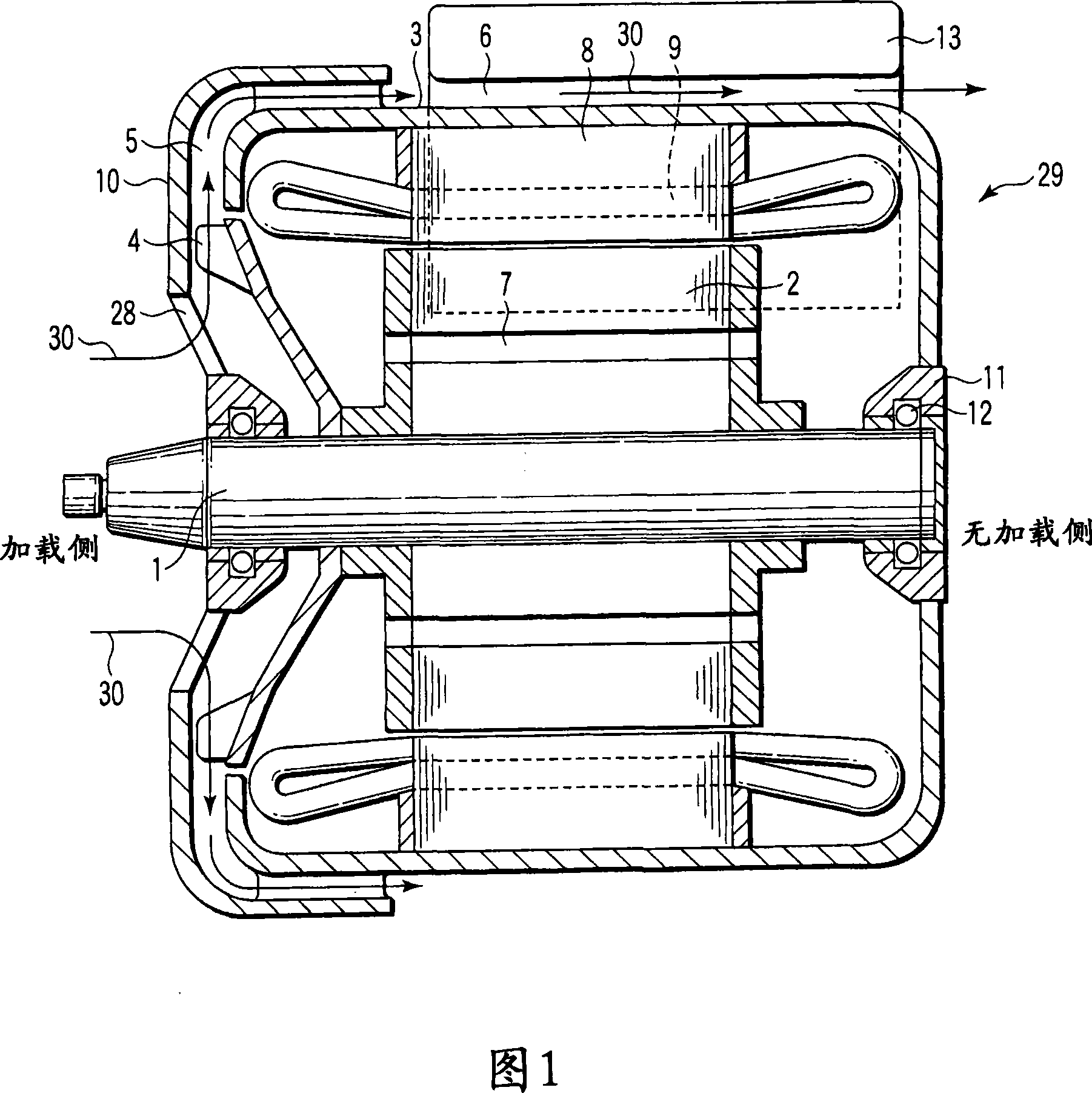
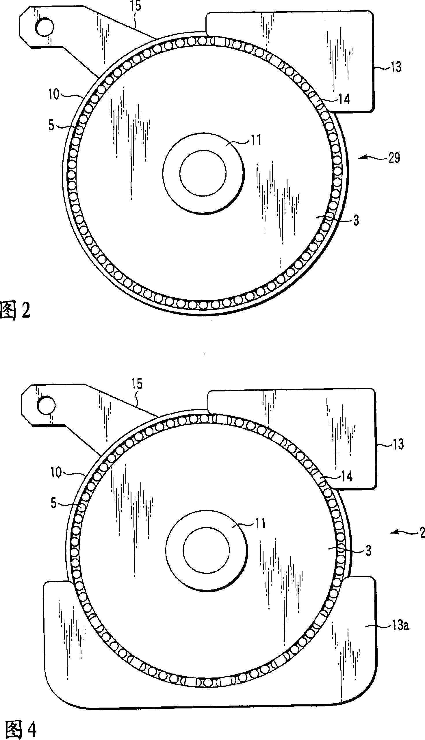
[0033] 1 is a vertical sectional view of a controller-integrated motor according to a first embodiment of the present invention. Fig. 2 is a cross-sectional view of the no-load side of the controller-integrated motor according to the first embodiment of the present invention. The same components in Figs. 17, 1 and 2 are denoted by the same reference numerals and will not be described in detail. The different components will be mainly described below. Repeated descriptions are also omitted in subsequent embodiments.
[0034] The current controller-integrated motor includes a motor body 29 and a controller 13 installed on the motor body 29 . The motor body 29 includes a frame 3, an end plate 10, a stator core 8, a stator coil 9, a rotor core 2, a shaft 1 that rotates to apply a driving force on the motor body 29, and an external fan 4 that discharges a cooling air flow 30 to cool the motor body 29 .
[0035] In the motor body 29 the external fan 4 is fitted around the shaft ...
no. 2 approach
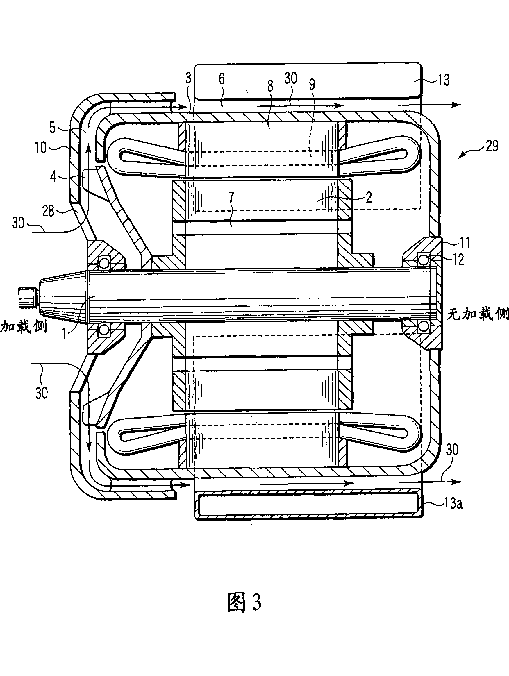
[0041] 3 is a vertical sectional view showing the structure of a controller-integrated motor according to a second embodiment of the present invention. 4 is a sectional view showing the structure of the no-load side of the controller-integrated motor according to the second embodiment of the present invention.
[0042] In the current controller-integrated motor, an upper controller 13 and a lower controller 13a are installed. The circuitry in the controller 13 is connected to the circuitry in the controller 13a. The connected circuits in the controllers 13 and 13a serve as a controller. A controller comprising a combination of controllers 13 and 13 a controls the motor body 29 . The rest of the structure is the same as that of the first embodiment.
[0043] The flow of cooling airflow 30 in the current controller integrated motor is similar to that in the first embodiment. Therefore, the cooling air flow 30 flows around the plurality of controllers 13 and 13a.
[0044] Acco...
no. 3 approach
[0046] 5 is a perspective view showing the structure of a controller for a controller-integrated motor according to a third embodiment of the present invention.
[0047] The controller-integrated motor according to the present embodiment is configured similarly to those according to the first and second embodiments except for the controller.
[0048] Current controller integrated motors have advancing airflow fins 16 and cooling airflow fins 17 on the face of the controller 13 .
[0049] The advancing airflow fins 16 are installed laterally (perpendicularly to the shaft 1 ) with respect to the motor main body 29 so as to allow the advancing airflow 31 caused by the motion of the vehicle to flow smoothly. The forward airflow fins 16 are preferably longer, but do not interfere with other components located around the motor body 29 .
[0050] Cooling air flow fins 17 are installed in the vertical direction (parallel to the shaft 1 ) so as to enable the cooling air flow 30 from t...
PUM
 Abstract
Description
Claims
Application Information
 - R&D
- Intellectual Property
- Life Sciences
- Materials
- Tech Scout
- Unparalleled Data Quality
- Higher Quality Content
- 60% Fewer Hallucinations
Browse by: Latest US Patents, China's latest patents, Technical Efficacy Thesaurus, Application Domain, Technology Topic, Popular Technical Reports.
© 2025 PatSnap. All rights reserved.Legal|Privacy policy|Modern Slavery Act Transparency Statement|Sitemap|About US| Contact US: help@patsnap.com


