Method and equipment for management control power supply of advanced telecommunication counting structure system
A technology for telecommunication computing and system power supply, which is applied in computing, transmission systems, telephone communications, etc. It can solve the waste of power resources, cannot support hot plug boards, and does not support independent management and control of power supply for rear plug boards/front conversion modules, etc. question
- Summary
- Abstract
- Description
- Claims
- Application Information
AI Technical Summary
Problems solved by technology
Method used
Image
Examples
Embodiment 1
[0115] In this embodiment, the second power conversion / control module added to the single board is set in the rear board, called the power conversion / control module, and a micro switch is added to the lower wrench of the rear board to control whether Supply power to the load circuit on the rear board.
[0116] FIG. 8 is a flowchart of a method for power management and control of an ATCA system in Embodiment 1 of the present invention. As shown in Figure 8, the method includes:
[0117] Step 801, separate the power supply provided to the rear board into management power and load power, and input the load power to the power conversion / control module of the rear board, and input the management power to the MMC of the rear board.
[0118] In step 802, the MMC of the rear board judges whether activation of the rear board is required according to user requirements, and if yes, executes step 803 and its subsequent steps, otherwise executes step 811 and its subsequent steps.
[0119...
Embodiment 2
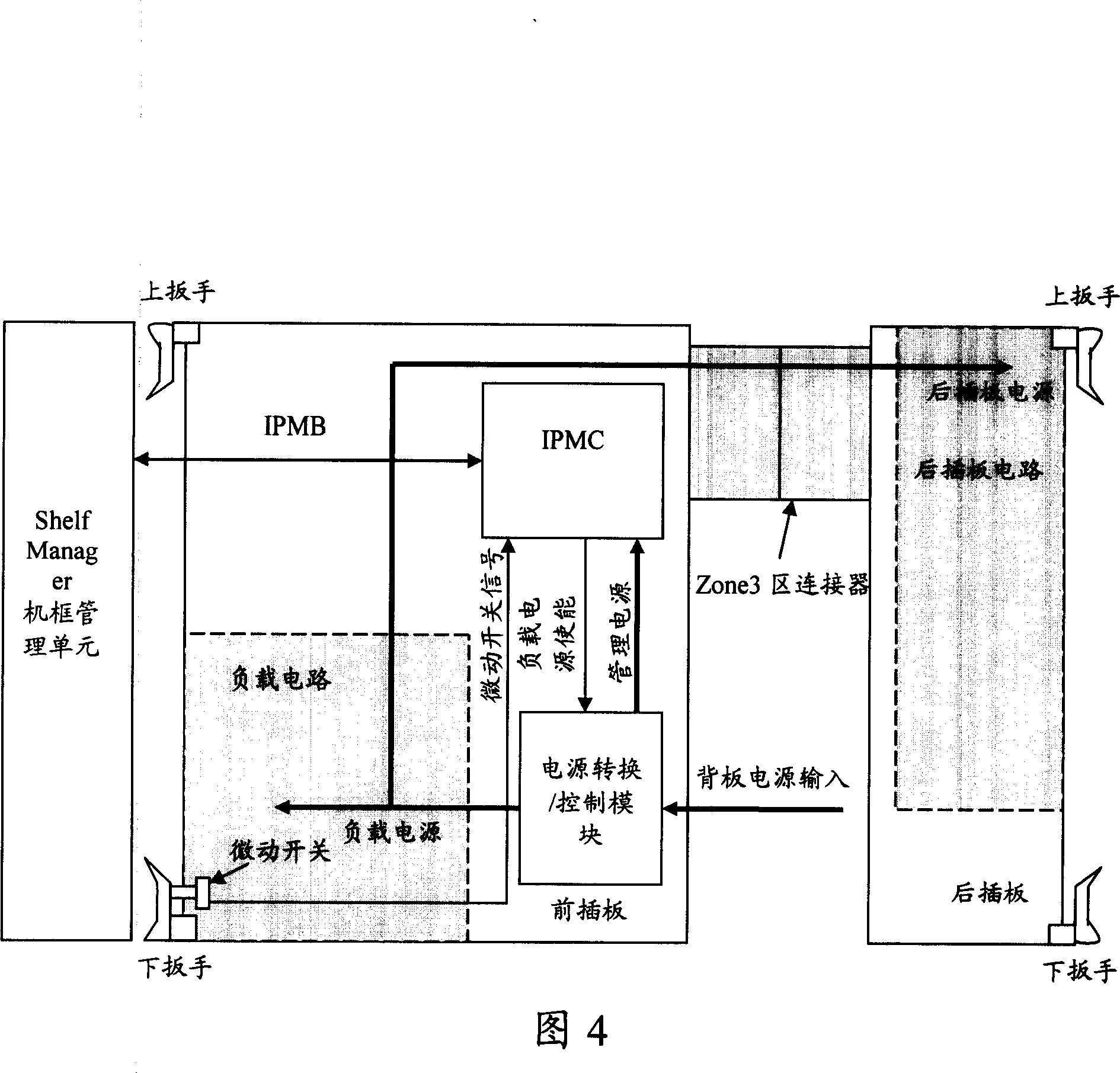
[0155] In this embodiment, the second power conversion / control module added to the single board is set in the front board, called the rear board load power conversion / control module, and a micro switch is added to the upper wrench of the rear board , to control whether to supply power to the load circuit of the rear board.
[0156] FIG. 10 is a flowchart of a method for power management and control of an ATCA system in Embodiment 2 of the present invention. As shown in Figure 10, the method includes:
[0157] Step 1001, separate the power supply provided to the rear board into management power and load power, and input the load power to the load power conversion / control module of the rear board, and input the management power to the MMC of the rear board.
[0158] In step 1002, the MMC of the rear board determines whether activation of the rear board is required according to the user's needs. If yes, execute step 1003 and its subsequent steps; otherwise, execute step 1010 and...
Embodiment 3
[0192] In this embodiment, the second power conversion / control module added to the single board is set in the front board. In addition to controlling the output of the load power of the rear board, the second power conversion / control module can also control the output of the rear board. The output of the management power supply is called the rear board power conversion / control module. A micro switch is added to the upper wrench of the rear board to control whether it needs to supply power to the load circuit of the rear board.
[0193] FIG. 12 is a flowchart of a method for power management and control of an ATCA system in Embodiment 3 of the present invention. As shown in Figure 12, the method includes:
[0194] Step 1201, input the power supply provided to the rear board to the power conversion / control module of the rear board, and the module separates the power supply into the load power of the rear board and the management power of the rear board.
[0195] Step 1202, the ...
PUM
 Abstract
Description
Claims
Application Information
 - R&D
- Intellectual Property
- Life Sciences
- Materials
- Tech Scout
- Unparalleled Data Quality
- Higher Quality Content
- 60% Fewer Hallucinations
Browse by: Latest US Patents, China's latest patents, Technical Efficacy Thesaurus, Application Domain, Technology Topic, Popular Technical Reports.
© 2025 PatSnap. All rights reserved.Legal|Privacy policy|Modern Slavery Act Transparency Statement|Sitemap|About US| Contact US: help@patsnap.com


