Clamp in use for testing LED

A technology for detecting fixtures and fixtures, which is applied in the parts of electrical measuring instruments, measuring electricity, measuring devices, etc., can solve the problems that affect the success rate of the probe lighting LED, cannot be disassembled, and high maintenance costs, and can meet the needs of manual labor. Feeding and automatic feeding, improving accuracy and success rate, the effect of product quality assurance

Inactive Publication Date: 2007-12-26
CHONGQING UNIV
View PDF0 Cites 19 Cited by
  • Summary
  • Abstract
  • Description
  • Claims
  • Application Information

AI Technical Summary

Problems solved by technology

The existing LED detection and sorting equipment has high technical content, high price, high maintenance cost, and relatively large volume; and because the current LED sorting system is basically imported from abroad, it is a whole that cannot be disassembled. inseparable
Therefore, for small enterprises that use LEDs in large quantities (such as assembling large-scale display screens with LEDs), there is currently no set of detection devices suitable for them that are only used for detection and classification, which is not conducive to the development and application promotion of the LED industry.
In addition, the LED inspection fixture in the existing LED manufacturing system needs to jointly control the positioning board and the probe during the test process, and must be synchronized with the front-end equipment. At the same time, the LED pins are small, which easily affects the probe's ability to light the LED. The success rate, that is, the accuracy of the detection is also poor

Method used


Image

  • Clamp in use for testing LED
  • Clamp in use for testing LED
  • Clamp in use for testing LED

Examples


Embodiment 1

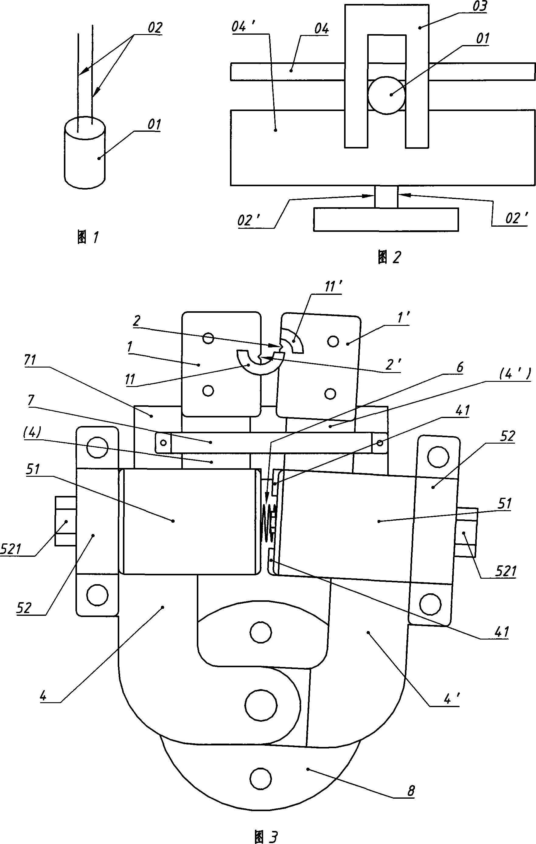
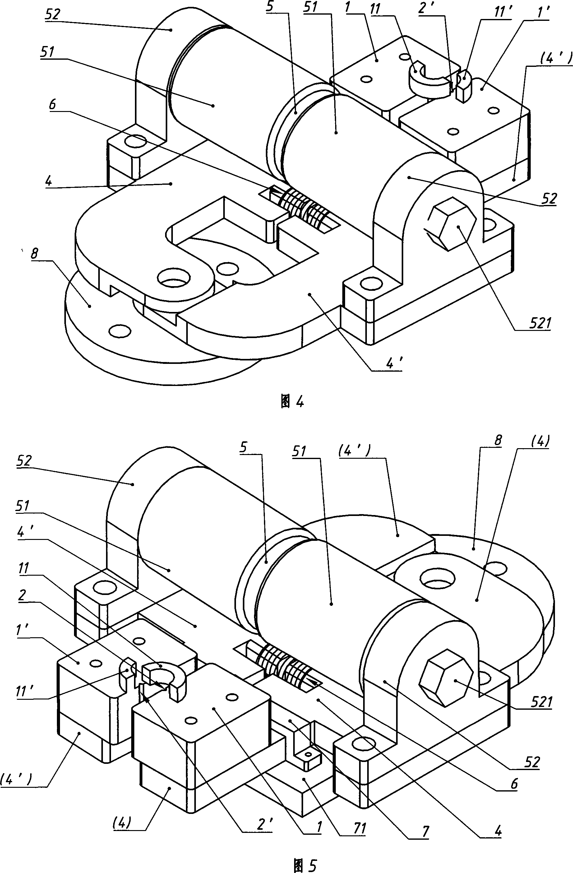
[0022] Embodiment 1 (with reference to the part marked 41 among Fig. 3 and Fig. 6):

[0023] The limiting part of this example is a limiting block 41 or a limiting nail installed on the inner side of a splint arm (swinging clamping arm 4' in the figure), and the limiting block 41 or limiting nail is opposite to another splint arm (In the figure, the inner surface of the fixed splint arm 4) is directly matched with it to limit the closing degree of the two splint arms (4, 4'); there is a straddle on the two splint arms (4, 4') Prevent them (4, 4 ') from excessively expanding the Π-shaped anti-expansion frame 7 (referring to Fig. ) on a pallet 71 below, wherein the fixed splint arm 4 is fixed together with the Π-shaped anti-expansion frame 7 or the pallet 71 with its outer surface against the inner surface of one side of the ∏-type anti-expansion frame 7 When the return spring 6 stretches the two splint arms (4, 4') until the inner surface of the other side of the anti-expansio...

Embodiment 2

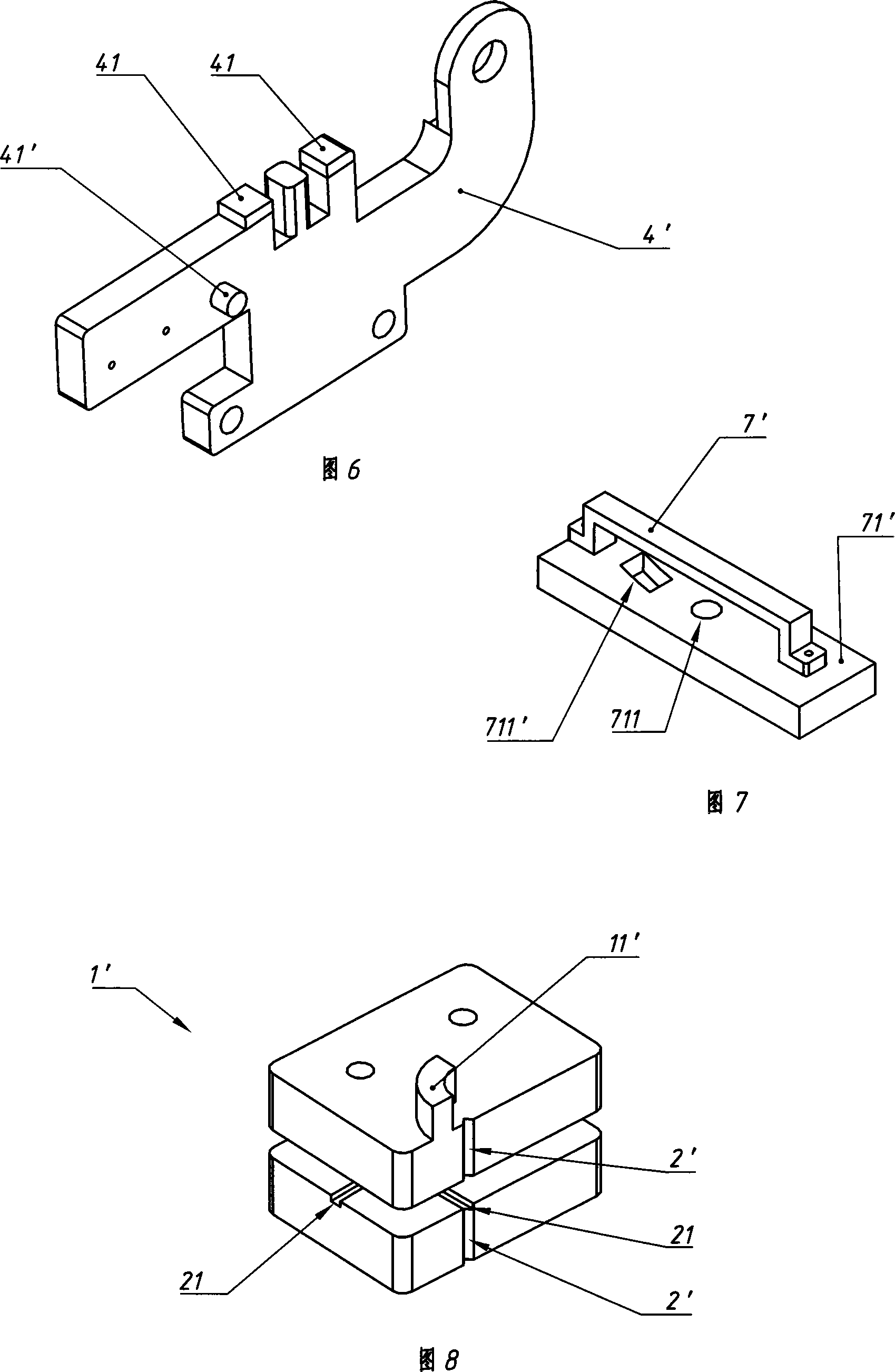
[0025] Embodiment 2 (with reference to the part marked 41' in Fig. 7 and Fig. 6):

[0026] In this example, two splint arms (4, 4') are straddled with a Π-shaped anti-error frame 7' that prevents them (4, 4') from staggering up and down. The two ends are fixed on a pallet 71' below the two splint arms (4, 4'), and the fixed splint arm 4 is fixed together with the ∏-type error-proof frame 7' or the pallet 71'. The limiting part of this example is the limiting pin 41' installed on the lower part of the swing splint arm 4', and the supporting plate 71' has an arc-shaped hole 711' matching the limiting pin 41'. What limits the closing degree of these two splint arms (4, 4') is that the inner surface of one end of the arc-shaped hole 711' on the pallet 71' that is finally fixed together with the fixed splint arm 4 is the limit pin 41' When the back-moving spring 6 stretches the two splint arms (4, 4 ') to the limit pin 41 ' and when the other end inner surface of the arc hole 711 ...


PUM


Abstract

A fixture used for carrying out LED detection is prepared for forming hinge clamping-plate by a fixed clamping plate arm swing clamping plate arm in order to hold LED, setting electric magnetic iron and reset spring between two said clamping plate arms, arranging space block to limit closing degree of clamping plate on at least one clamping plate arm and setting a pair of material-receiving paws on end of two said clamping plate arms for holding tested LED.

Description

technical field [0001] The invention relates to a fixture for detecting LEDs. Background technique [0002] With the breakthrough of some key technologies of LED (commonly known as light-emitting diode) and the expansion of application scope, LED has been hailed as "the new light source of the 21st century" by domestic and international industry insiders. In order to ensure the quality of LEDs, its testing and sorting are extremely important. Existing LED testing fixtures are generally used for online testing and sorting on LED production lines, and are an intermediate link in the LED manufacturing system. Most of the LED testing fixtures use parallel splints (see 04 and 04' in Figure 2). ) Position the LED (see 01 in Figure 1 and 2), press the LED pin (see 02' in Figure 2) with a probe (see 02' in Figure 1) and turn it on for testing. The sorting equipment is based on The detection parameters are divided into files, and the material is unloaded at a suitable position. T...

Claims


Application Information

Patent Timeline
Patent Type & Authority Applications(China)
IPC IPC(8): G01R1/02G01R31/00G01R31/02G01R31/26
Inventor 秦岚吕云日刘俊
Owner CHONGQING UNIV
Why Eureka
Try Eureka