Back light module and light guiding plate set
A technology of backlight module and light guide plate, which is applied in the direction of light guide, optics, optical components, etc., and can solve the problems of lack of products and inconvenience
- Summary
- Abstract
- Description
- Claims
- Application Information
AI Technical Summary
Problems solved by technology
Method used
Image

Examples
no. 1 example
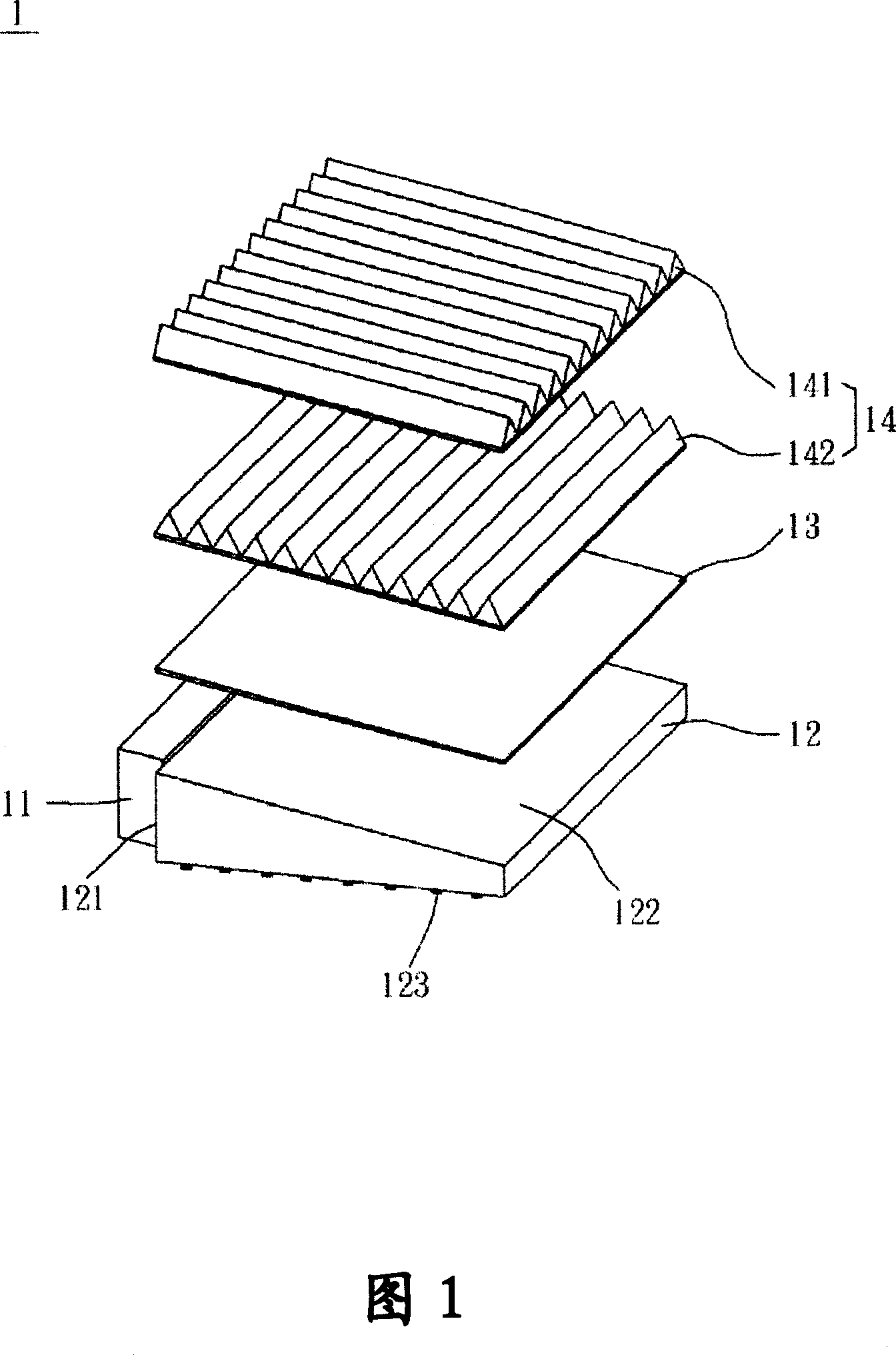
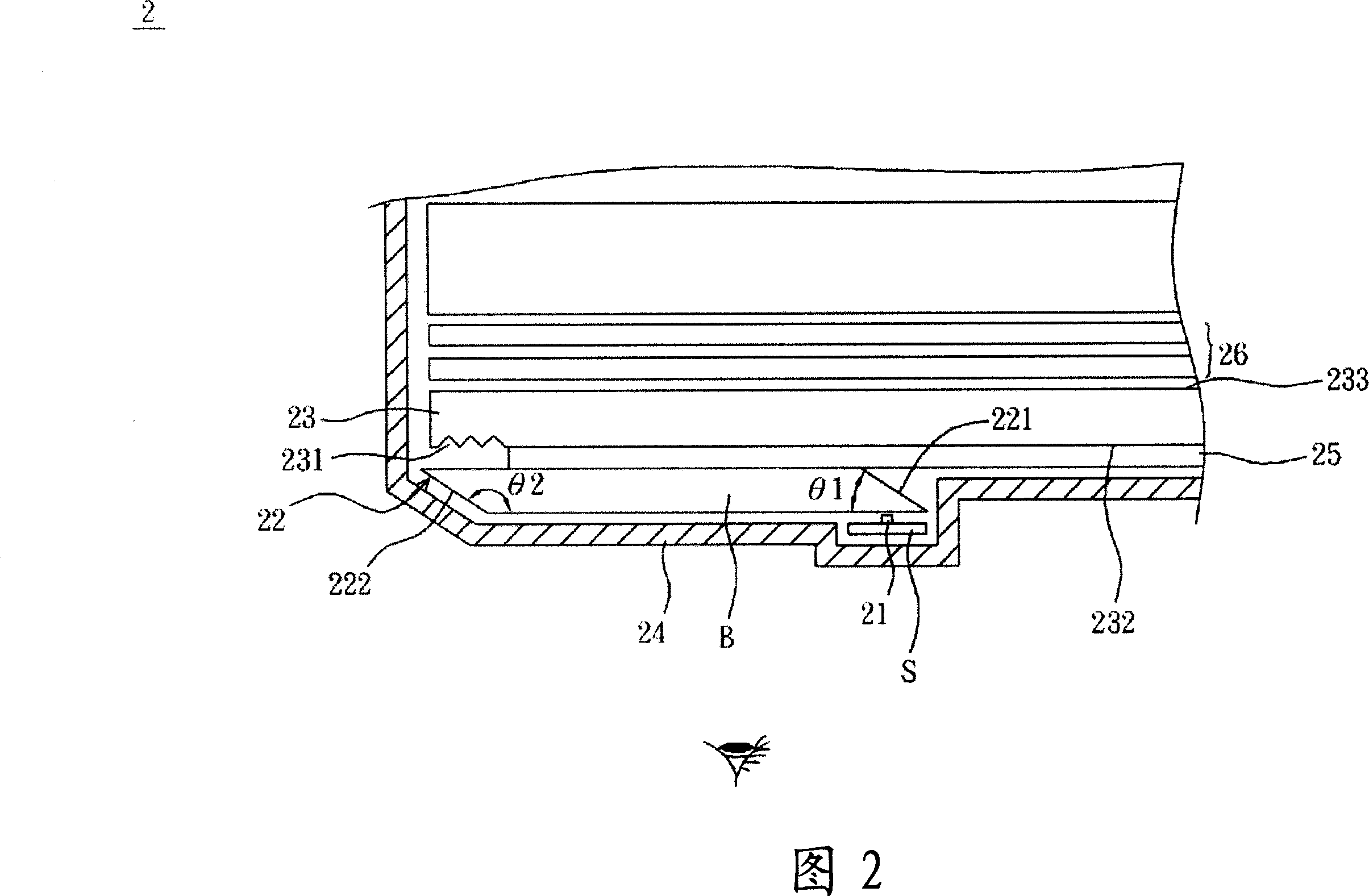
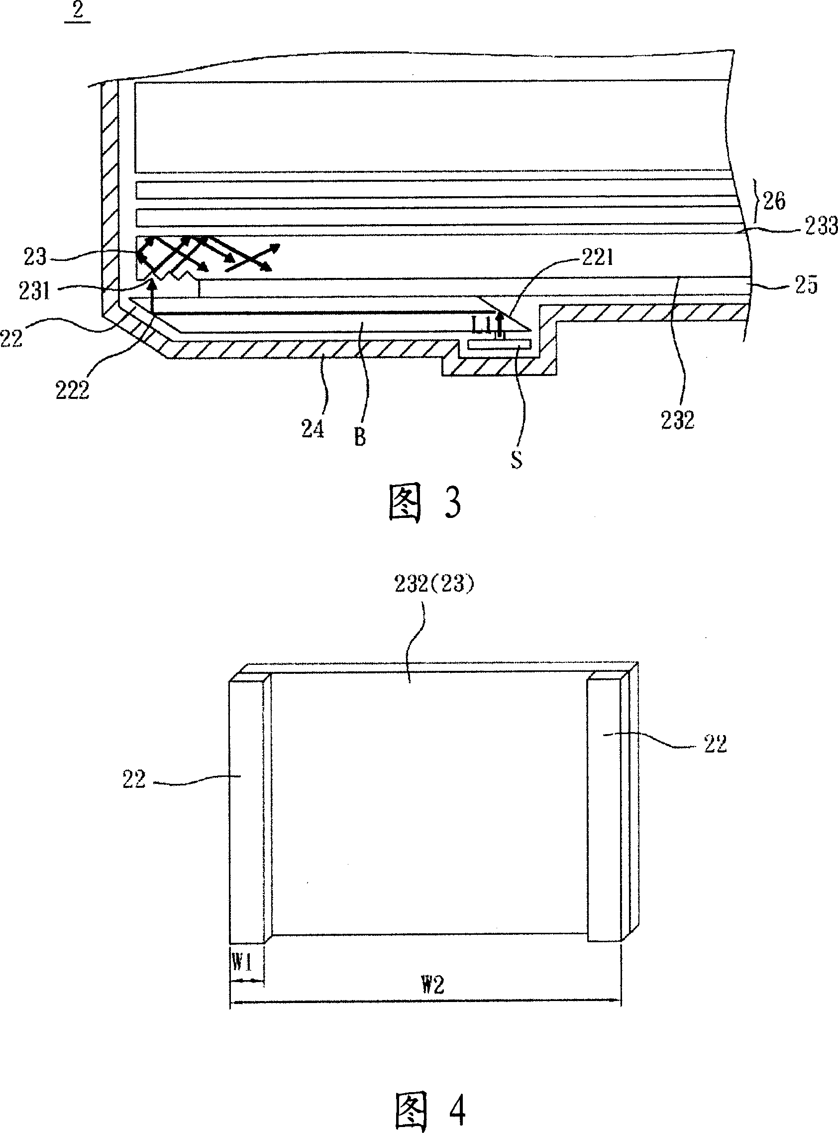
[0078] As shown in FIG. 2, the backlight module 2 includes a first light source 21, a first light guide plate 22 and a second light guide plate 23. Among them, the first light guide plate 22 and the second light guide plate 23 can be collectively referred to as a light guiding plate assembly.
[0079] The first light source 21 is adjacent to the first light guide plate 22. The first light source 21 can be a light-emitting diode, a laser diode or a plurality of light-emitting diodes. If it is a plurality of light-emitting diodes, they can have different colors. In addition, the first light source 21 may be disposed on a printed circuit board S, and the backlight module 2 may further include a back plate 24. The first light source 21 is disposed on the back plate 24 by the printed circuit board S.
[0080] In this embodiment, the first light guide plate 22 includes a first inclined surface 221, a second inclined surface 222, and a first light guide plate body B. The first inclined s...
no. 2 example
[0087] In this embodiment, the difference from the first embodiment is that the first light guide plate 22 in the first embodiment is a parallelogram plate, and in this embodiment, referring to FIG. 6, the original first light guide plate The sharp angle between the first inclined surface 221 of 22 and the first light guide plate 22 is cut or polished to form a larger angle, for example, ninety degrees (indicated by the circular dashed line). However, the first light guide plate body B still forms a first angle θ1 and a second angle θ2 with the first inclined surface 221 and the second inclined surface 222, respectively, and the sum of the second angle θ2 and the first angle θ1 is 180 degrees.
no. 3 example
[0089] Please refer to FIGS. 2 and 7 at the same time, the backlight module 3 further includes a second light source 27, and the first light guide plate 22 further includes a third inclined surface 223. The second light source 27 may have a different color from the first light source 21 for light mixing or the second light source 27 may have a plurality of light emitting diodes of different colors for light mixing. The third inclined surface 223 is adjacent to the first inclined surface 221 at one end of the first light guide plate body B. In this way, a second light beam L2 emitted by the second light source 27 enters the first light guide plate body B, is reflected by the third inclined surface 223 and the second inclined surface 222, and exits the first light guide plate 22.
[0090] In addition, the backlight module 3 further includes a plurality of focusing lenses F, which are located on the light path of the light beams emitted by each light source entering the first light g...
PUM
 Abstract
Description
Claims
Application Information
 - R&D
- Intellectual Property
- Life Sciences
- Materials
- Tech Scout
- Unparalleled Data Quality
- Higher Quality Content
- 60% Fewer Hallucinations
Browse by: Latest US Patents, China's latest patents, Technical Efficacy Thesaurus, Application Domain, Technology Topic, Popular Technical Reports.
© 2025 PatSnap. All rights reserved.Legal|Privacy policy|Modern Slavery Act Transparency Statement|Sitemap|About US| Contact US: help@patsnap.com