Communication system and communication method

A communication system and communication media technology, applied in the field of communication systems, can solve problems such as inability to continue communication, difficult settings for users, and increased possibility of wrong settings

Inactive Publication Date: 2007-12-26
NEC CORP
View PDF0 Cites 4 Cited by
  • Summary
  • Abstract
  • Description
  • Claims
  • Application Information

AI Technical Summary

Problems solved by technology

[0015] However, even if the reliability of the link between adjacent nodes is improved, the two communicating nodes cannot communicate only due to accidents such as failure of any relay node on the communication path
[0016] In addition, since link aggregation is applicable only between two nodes adjacent to each other, it cannot be applied to a network in which two communicating nodes are connected through multiple communication paths including one or more relay nodes.
[0017] Also, when OSPF and BGP routing protocols are used, since it takes time to detect a failure on the communication path, communication cannot be continued until the failure is detected
[0018] And, even if a failure is detected, since it takes time to obtain a communication path that does not have a failure again, the period before restarting communication by switching from a communication path that has failed to a communication path that does not have a failure time, communication will be interrupted
[0019] In addition, since detailed and advanced knowledge about Link Aggregation is required to set Link Aggregation, it is difficult for general users to perform the setting, which increases the possibility of wrong settings and makes it impossible to efficiently use the network.
[0020] Next, in the failure detection method used in combination with NAT technology, that is, in the method in which nodes performing communication detect a failure on the communication path by sending and receiving monitoring packets (such as PING packets) specifying the respective counterpart nodes as destinations , as the number of counterpart nodes increases, the number of monitoring packets sent also increases, so the processing load for detecting failures is very large
[0021] In addition, since it is necessary to set the destination addresses of all counterpart nodes, as the number of counterpart nodes increases, the number of items to be set also increases, thus increasing the possibility of wrong settings by the network administrator.

Method used


Image

  • Communication system and communication method
  • Communication system and communication method
  • Communication system and communication method

Examples


no. 1 approach

[0065] A first embodiment of the present invention will be described in detail with reference to the drawings.

[0066] (Structure of Communication System)

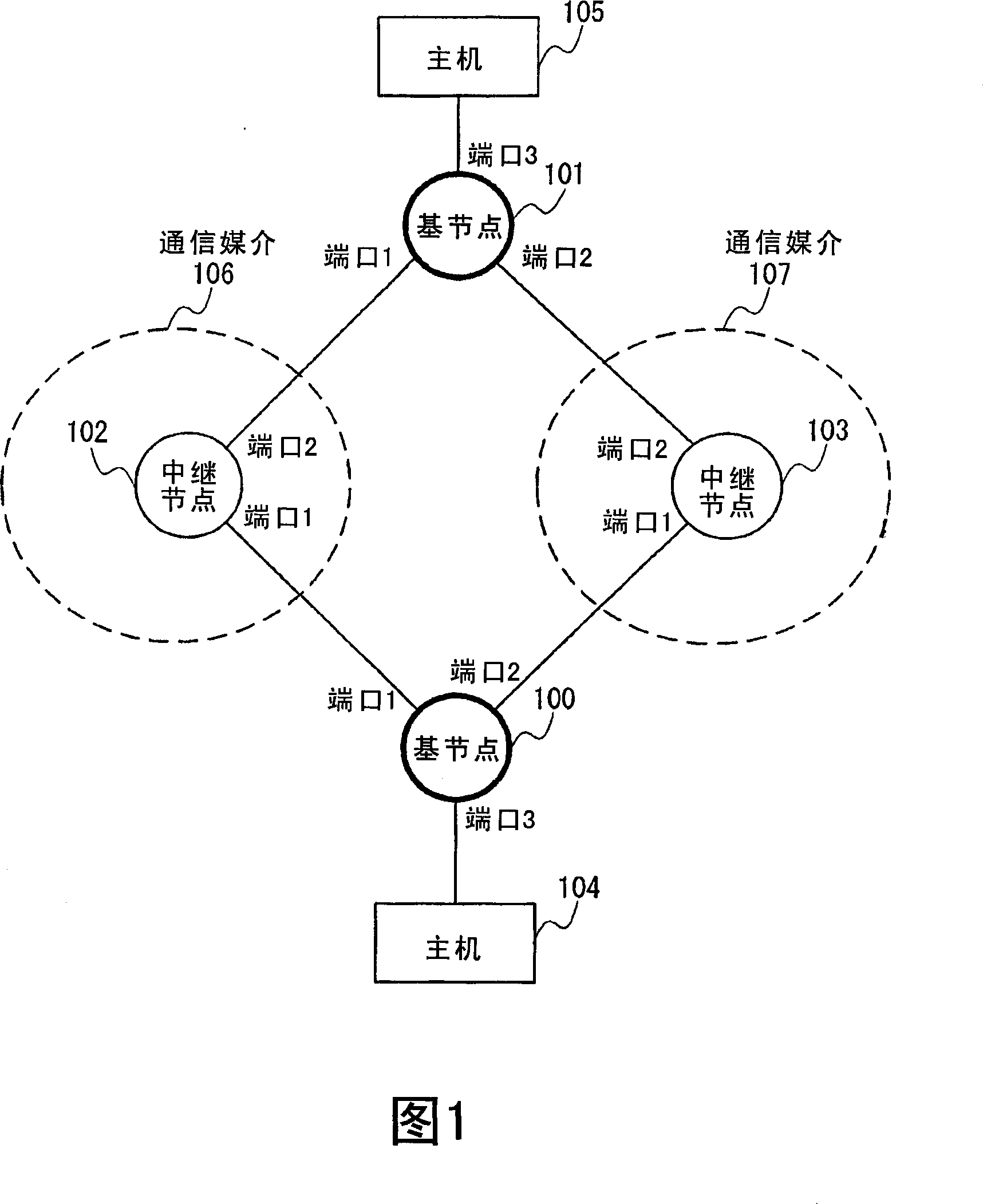
[0067] FIG. 1 shows the configuration of a communication system in the first embodiment of the present invention.

[0068] The communication system shown in Fig. 1 comprises: two base nodes 100 and base node 101; The communication medium 106 that is made up of relay node 102 and the communication medium 107 that are made up of relay node 103; And two hosts, namely host 104 and Host 105.

[0069] Here, a relay node is a node constituting a communication medium for relaying a data frame sent by a base node and transferring it to a predetermined destination.

[0070] In addition, the base node is a node connected to the communication medium. Any number of hosts are arranged directly or via more than one node on the interface belonging to the base node but not connected to the communication medium. The data frames sent by t...

no. 2 example

[0257] A second embodiment of the present invention will be described in detail with reference to the drawings.

[0258] A method of providing a communication system using a port mapping table and having high reliability is described in the second embodiment.

[0259] (Structure of Communication System)

[0260] Since the structure of the communication system in the second embodiment is the same as the structure of the communication system in the first embodiment shown in FIG. 1 , description is omitted.

[0261] (the structure of the base node)

[0262] FIG. 7 is a block diagram showing the structure of base nodes 100 to 101 in the second embodiment.

[0263] The structure of the base node 100 (the base node 101 is the same) in the second embodiment is different from the first embodiment in that the base node 100 has a port mapping table 701 and a port conversion unit 702 .

[0264]By assigning a port number, which is information for uniquely identifying the virtual port, ...

no. 3 example

[0317] A third embodiment of the present invention will be described in detail with reference to the drawings.

[0318] In the third embodiment, a method for realizing high reliability in a communication system in which three or more base nodes are connected to a communication medium is described.

[0319] (Structure of Communication System)

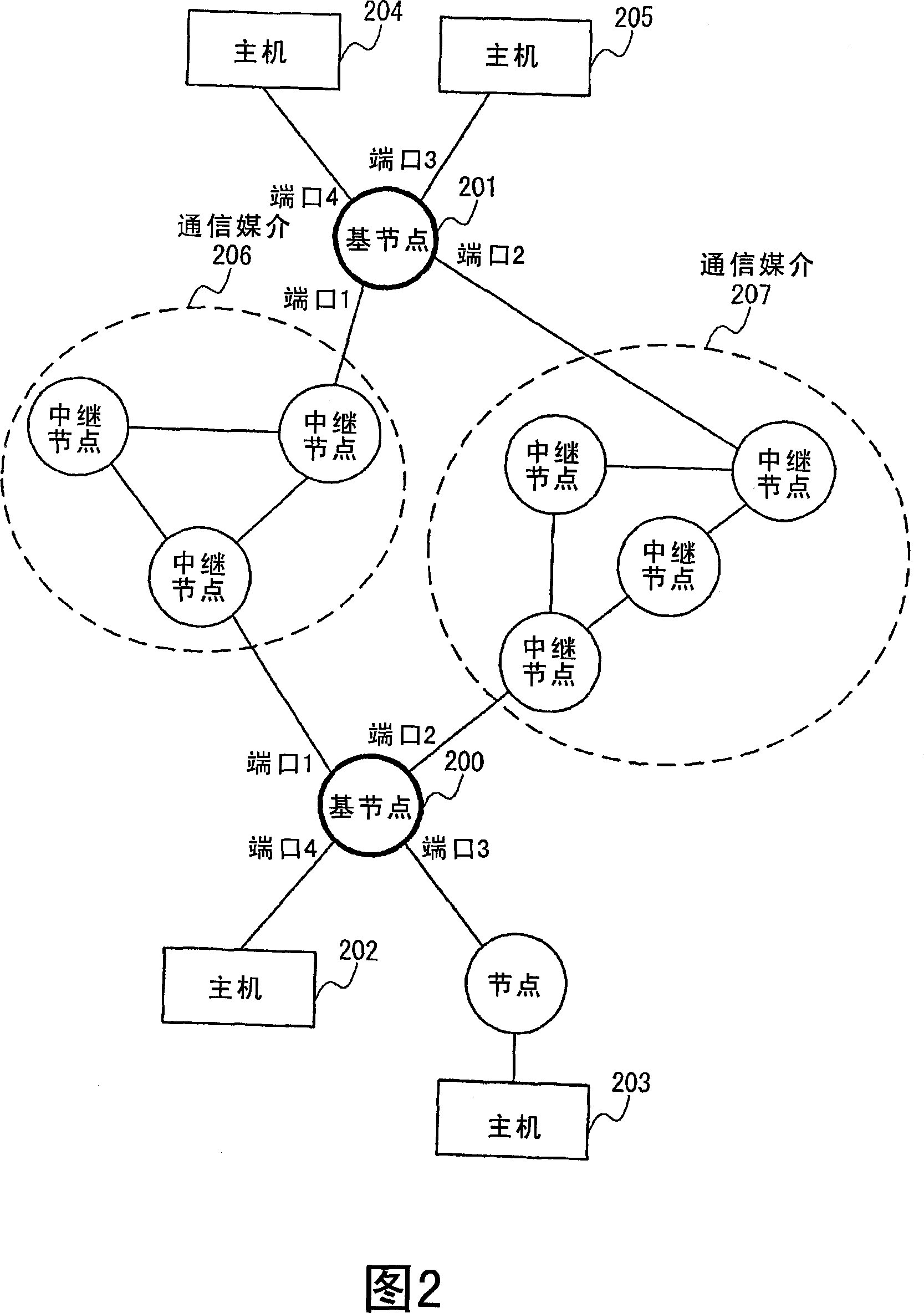
[0320] Fig. 10 shows the configuration of a communication system in the third embodiment.

[0321] The communication system structure in the third embodiment differs from the first and second embodiments in that three base nodes 100, 101, 1000 are connected to two communication media 106, 107. The base node 1000 is connected to the relay node 102 on port 1, connected to the relay node 103 on port 2, and connected to the host 1001 on port 1.

[0322]Although in the communication system shown in FIG. 10, three base nodes, base node 100, base node 101, and base node 1000, are connected to communication media 106-107, there may be more tha...


PUM


Abstract

Each of hub nodes (100,101) transmits, from its ports (1,2), keep-alive frames to be broadcasted by relay nodes constituting communication media (106,107). Arrivals of the keep-alive frames are monitored at the respective ports. During a normal state, the two communication media connected to the ports (1,2) are used virtually as a single node so as to expand the communication band. During detection of a trouble, only the communication medium, which is connected to a port where no trouble has been detected, is used to continue the communication.

Description

technical field [0001] The present invention relates to a communication system that realizes high reliability, and particularly to a communication system with high reliability that transmits data frames using a plurality of bandwidth to suppress congestion, and when a failure is detected, communication continues using only the communication path where the failure was not detected. Background technique [0002] In recent years, computer networks have made great progress in various fields of society. They are not only widely used as communication means for information transmission by email and information disclosure by Web sites, but also play an important role as an infrastructure for providing various services. social role. [0003] In today's society that cannot be separated from computer networks, due to accidents such as failure of devices constituting the network, cuts of communication cables, or narrowing of the communication bandwidth due to congestion, etc., events t...

Claims


Application Information

Patent Timeline
Patent Type & Authority Applications(China)
IPC IPC(8): H04L12/56H04W40/22H04W40/24
CPCH04W40/22H04W40/24
Inventor 小笠原大作厩桥正树榎本敦之飞鹰洋一岩田淳阿留多伎明良
Owner NEC CORP
Why Eureka
Try Eureka