Dust collection device for an handheld electrical tool

A technology for electric tools and dust collection, which is applied in the direction of portable motorized devices, manufacturing tools, striking tools, etc. It can solve the problems of reduced suction power, clogged dust filter, severe damage, etc., and achieve the effect of reduced suction power

Active Publication Date: 2008-01-02
ROBERT BOSCH GMBH
View PDF0 Cites 11 Cited by
  • Summary
  • Abstract
  • Description
  • Claims
  • Application Information

AI Technical Summary

Problems solved by technology

After a certain volume of process dust has been conveyed, the dust filter becomes increasingly clogged, so that the suction power is reduced and the container needs to be emptied

Method used


Image

  • Dust collection device for an handheld electrical tool
  • Dust collection device for an handheld electrical tool
  • Dust collection device for an handheld electrical tool

Examples


Embodiment Construction

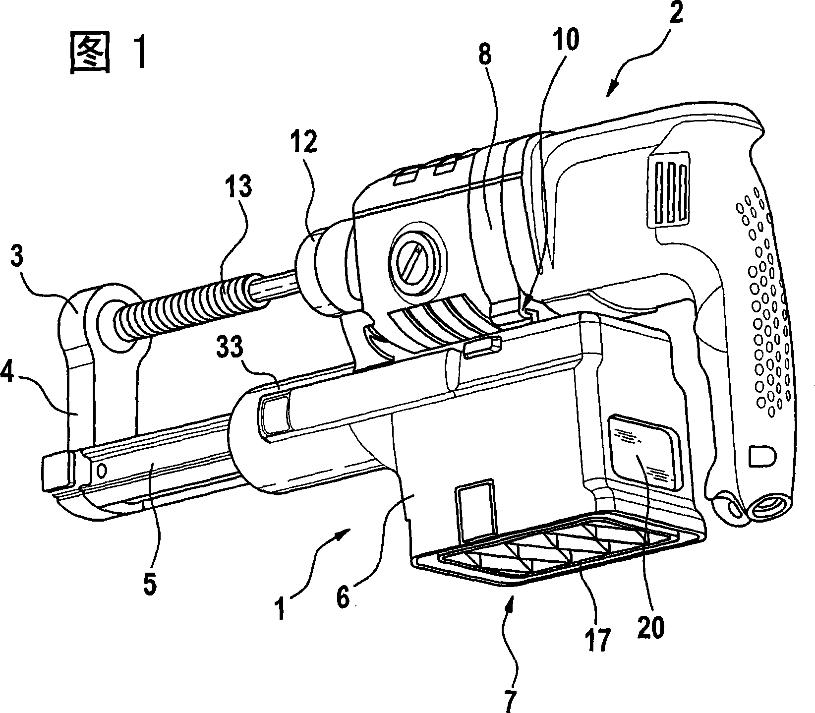
[0023] FIG. 1 shows a dust collection device 1 which is detachably and lockably connected to a hand-held power tool 2 . The hand-held power tool is a percussion drill. Instead of a hammer drill, conventional drills or hammer drills can also be used.

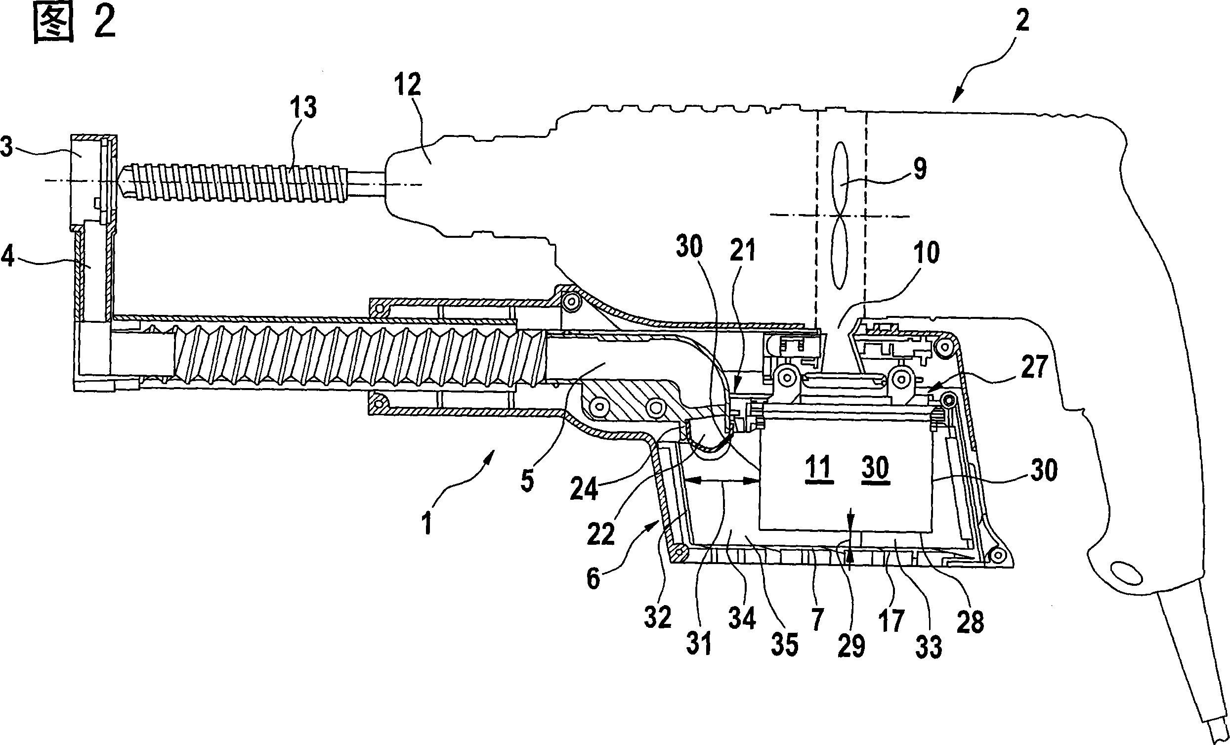
[0024] The dust collecting device 1 has a dust suction opening 3 which is connected via a suction channel 4 and a telescopic suction channel 5 to a housing 6 which can be removed by means of a suitable detachable The locking mechanism is fixed on the hand-held electric power tool 2 . In the housing 6 there is a dust container 7 which can be removed downwards. The hand-held power tool 2 has a suction module 8 , whose suction fan impeller 9 ( FIG. 2 ) is driven by the drive motor of the hand-held power tool 2 . The suction fan wheel 9 is connected via a chimney-shaped suction channel 10 to the dust container 7 via a replaceable dust filter 11 ( FIG. 2 ).

[0025] As can be seen from FIG. 1 , a drill bit 13 is clamped into the t...


PUM


Abstract

The invention relates to a dust collection device for an handheld electrical tool (2) for processing dust in aid of airflow delivery, comprising at least one dust filter. The dust filter (11) is in a hanging manner at working position during a horizontal work-tool operation and at least one dust collecting chamber (35) is provided in an air flow direction.

Description

technical field [0001] The invention relates to a dust collection device of a hand-held electric power tool for machining dust conveyed by means of an air flow, having at least one dust filter. Background technique [0002] Dust collection devices for hand-held electric power tools are known. The processing dust generated at the processing point is transported away from the processing point by means of the negative pressure by means of the air flow and into the separating container. Has a dust filter in the separation container for clean air flow. The cleaned air flows out from the air outlet of the dust collection device or—if a suction device is provided in the hand-held power tool—from the latter. [0003] It is known to arrange a separating container provided with a dust filter in the region of the dust suction opening in the vicinity of a tool, for example a drill bit of a hand-held power tool. A disadvantage is that the volume of the separating device can only be de...

Claims


Application Information

Patent Timeline
Patent Type & Authority Applications(China)
IPC IPC(8): B25F5/00B25D17/18B23B45/02
CPCB23Q11/0046
Inventor O·鲍曼T·伯恩哈特H·施密德J·伦纳茨J·博赫特
Owner ROBERT BOSCH GMBH
Why Eureka
Try Eureka