Post-pouring type deformation device and construction method thereof
A technology of deformation device and construction method, applied in building components, building thermal insulation materials, etc., can solve the problems of prolonging the construction period, unable to backfill with soil, affecting the construction period, etc., to reduce internal stress and stress concentration areas, and solve the problem of affecting the construction period. The contradiction and the effect of convenient construction
- Summary
- Abstract
- Description
- Claims
- Application Information
AI Technical Summary
Problems solved by technology
Method used
Image
Examples
Embodiment 1
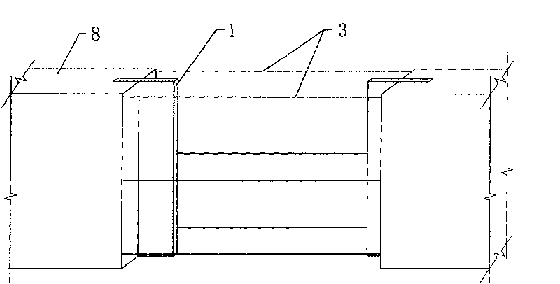
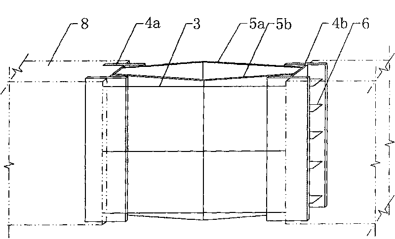
[0048] Embodiment 1 of the present invention is as Figure 3-4 As shown, the post-cast deformation device described in this embodiment is a post-cast deformation device specially suitable for basement side walls. The construction method of the post-cast deformation device specifically includes the following steps:
[0049] (1). Formwork 7a, 7b for making the side wall of the basement. The second formwork 7a, 7b are located on both sides of the side wall respectively, and the steel bars 3 are arranged in a criss-cross pattern; at the same time, the post-cast deformation device of the box structure is produced. : I-beams 4a, 4b and zigzag steel plates 5a, 5b are welded and fixed, so that the webs 41 of the two I-beams 4a, 4b are parallel, and the "I" end faces of the two are relatively aligned, and the two zigzag steel plates 5a , 5b are located between the two I-beams 4a, 4b, and the zigzag-shaped steel plates 5a, 5b are bent along their center lines, and are composed of two mu...
Embodiment 2
[0057] Embodiment 2 of the present invention is as Figure 5 , Image 6 As shown, the post-cast deformation device described in this embodiment is a post-cast deformation device specially suitable for floor slabs. The difference between the construction method of the post-cast deformation device and Embodiment 1 is that the post-cast deformation device Only one meander-shaped steel plate 5 is included.
[0058] Correspondingly, in step (1), the formwork 7 of the floor is made, and the formwork 7 is located below the floor. The straight side and the webs 41 of the two I-beams 4a and 4b on both sides are welded and fixed, and the corner opening of the zigzag steel plate 5 faces downward; the post-casting deformation device is pre-embedded in the formwork 7, so that the I-beam 4a The flange 42 of , 4b is parallel to the template 7 of the floor, and then the I-beam 4a, 4b of the post-casting deformation device is welded and fixed with the reinforced bar 3 ( Figure 5 In the thr...
Embodiment 3
[0060] Embodiment 3 of the present invention is as Figure 7~1 0, the post-cast deformation device described in this embodiment is a post-cast deformation device specially suitable for floor slabs. The difference from the previous embodiment is that the post-cast belt deformation device is a segmented structure: deformation The device is broken into two sections along the direction parallel to the end faces of the I-beams 4a and 4b, and there is a gap between the adjacent two sections, and seals are fixed on the end faces of the two adjacent I-beams 4a and 4b at the break steel plate9. This embodiment is especially suitable for the following situation: when the post-casting tape intersects with the frame beam 11, the post-casting tape is broken at the place where it interferes with the frame beam 11, that is, it is divided into two sections by the frame beam 11. An "L" shaped anchor bar 10 is fixed on the sealing steel plate 9, and one end of the anchor bar 10 is fixed on the...
PUM
 Abstract
Description
Claims
Application Information
 - R&D
- Intellectual Property
- Life Sciences
- Materials
- Tech Scout
- Unparalleled Data Quality
- Higher Quality Content
- 60% Fewer Hallucinations
Browse by: Latest US Patents, China's latest patents, Technical Efficacy Thesaurus, Application Domain, Technology Topic, Popular Technical Reports.
© 2025 PatSnap. All rights reserved.Legal|Privacy policy|Modern Slavery Act Transparency Statement|Sitemap|About US| Contact US: help@patsnap.com


