Wall building machine

A technology of wall-laying machine and frame, which is applied in the direction of construction, building structure, and building material processing, etc., which can solve the problems of inability to realize simultaneous operations, and achieve the effects of high automation, stable and reliable quality, and high work efficiency

Inactive Publication Date: 2008-01-09
刘金前
View PDF1 Cites 39 Cited by
  • Summary
  • Abstract
  • Description
  • Claims
  • Application Information

AI Technical Summary

Problems solved by technology

However, due to the limitations of the design structure, it can only simply replace the workload of one person, and t

Method used


Image

  • Wall building machine
  • Wall building machine

Examples


Example Embodiment

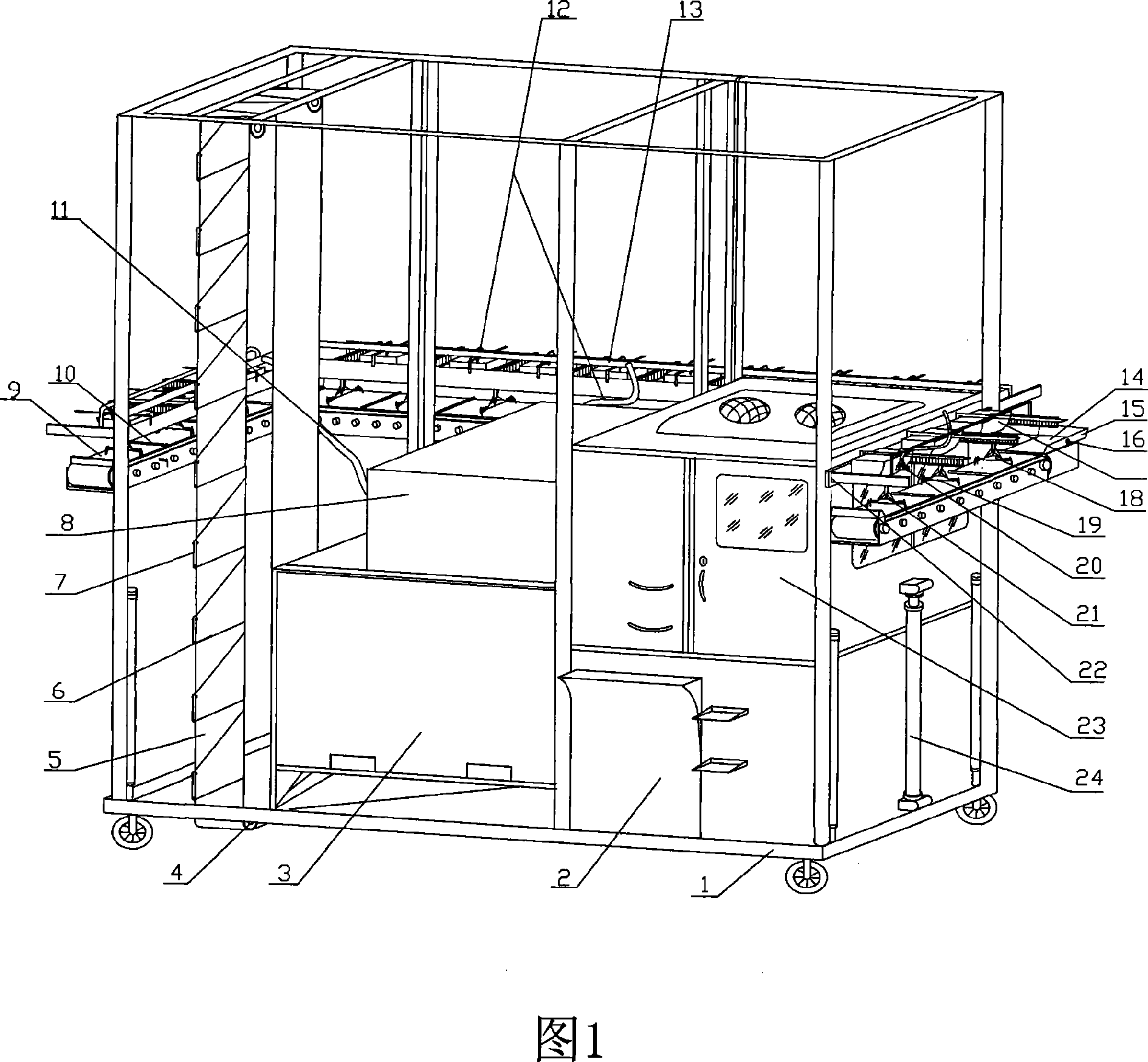
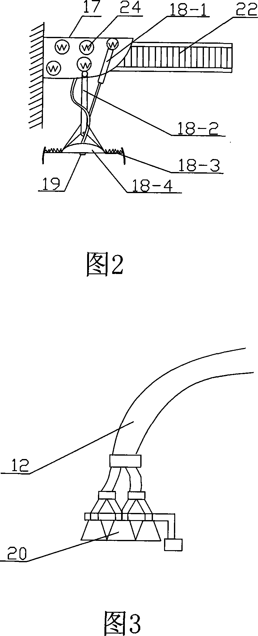
[0015] The present invention will be further elaborated below in conjunction with the accompanying drawings. As shown in Figure 1, the main structure of the present invention comprises brick placement box 3, brick delivery device, mortar placement box 2, mortar delivery unit, control device and bricklaying machine head 17, the brick outlet of brick placement box 3 Corresponding to the brick lifting and conveying device, the brick outlet of the brick lifting and conveying device corresponds to the brick horizontal conveying device on one side of the frame 1, and the brick horizontal conveying devices on each side are sequentially connected by the brick steering device 14, The mortar placement box 2 is connected to the bricklaying machine head 17 side by the pressure box 8 and the mortar delivery main pipe 11 of each side. On the bricklaying machine head 17, the mortar shunt filling pressure head 21 is fixedly installed, and the bricklaying machine head 17 is evenly spaced on th...


PUM


Abstract

A bricklaying machine includes machine bracket, brick hopper, brick transmission device, mortar hopper, mortar transmission device and control device. The bricklaying device is installed to the end of the brick and mortar transmission device. The outlet of brick hopper is connected to brick lifting device which is connected to a brick horizontal transmission device. Mortar hopper is connected to bricklaying device through pressure box and transmission pipe. At the end of the transmission pipe, it is installed with mortar paving nozzle and distribution nozzle. Bricklaying device is fixed on the bracket above brick horizontal transmission device with lifting device between the bracket and the main body.

Description

(1) Technical field: [0001] The invention relates to construction machinery, in particular to a wall-laying machine integrating grouting, brick-laying and extrusion. (two) background technology: [0002] At present, the walls of houses are mostly made of red bricks or cement bricks according to a certain stacking method and are manually built. The efficiency of manual wall building is low and the labor intensity is high. For this reason, the someone has also invented mechanical wall-building machine. Wherein, my country's patent No. is that 03221973.3 patent number discloses a kind of automatic wall-laying machine, and it mainly is made up of control device, brick hopper, mortar hopper, compacting grouting device, material delivery device. However, due to the limitations of the design structure, it can only simply replace the workload of one person, and the production efficiency has not been significantly improved, let alone simultaneous operations in several directions. ...

Claims


Application Information

Patent Timeline
IPC IPC(8): E04G21/22
Inventor 刘金前
Owner 刘金前
Why Eureka
Try Eureka