Bidimensional/three-dimensional image switching display device

A technology of three-dimensional image and display device, which is applied in the direction of identification device, static indicator, optics, etc., to achieve the effect of reducing the thickness and weight of the assembly, and reducing the number of components

Inactive Publication Date: 2008-01-09
WINTEK CORP
View PDF0 Cites 19 Cited by
  • Summary
  • Abstract
  • Description
  • Claims
  • Application Information

AI Technical Summary

Problems solved by technology

[0003] However, when this known design intends to achieve the display effect of the above-mentioned 2D/3D image switching, because the liquid crystal display panel 110, the liquid cry

Method used


Image

  • Bidimensional/three-dimensional image switching display device
  • Bidimensional/three-dimensional image switching display device
  • Bidimensional/three-dimensional image switching display device

Examples


Embodiment Construction

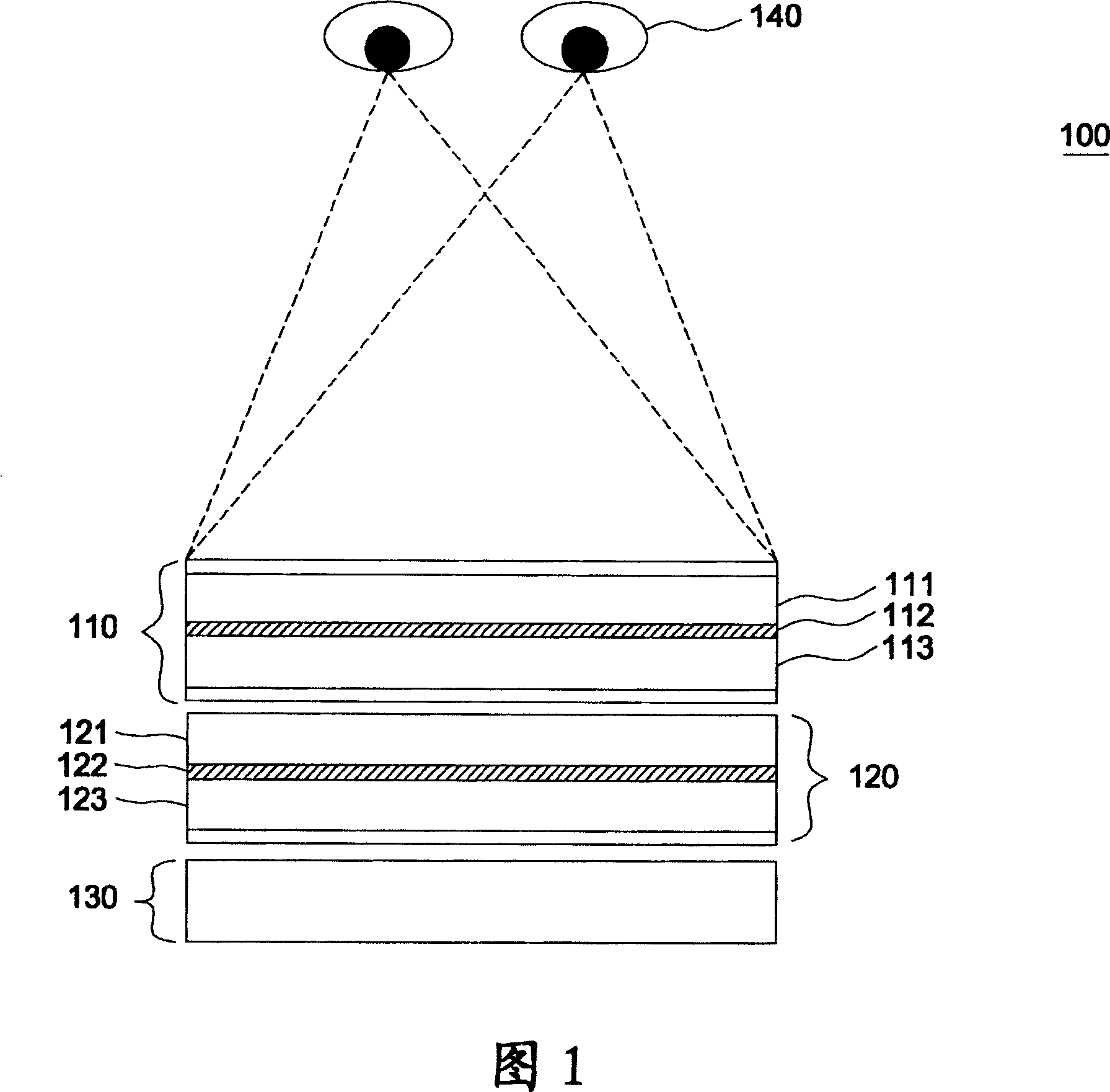
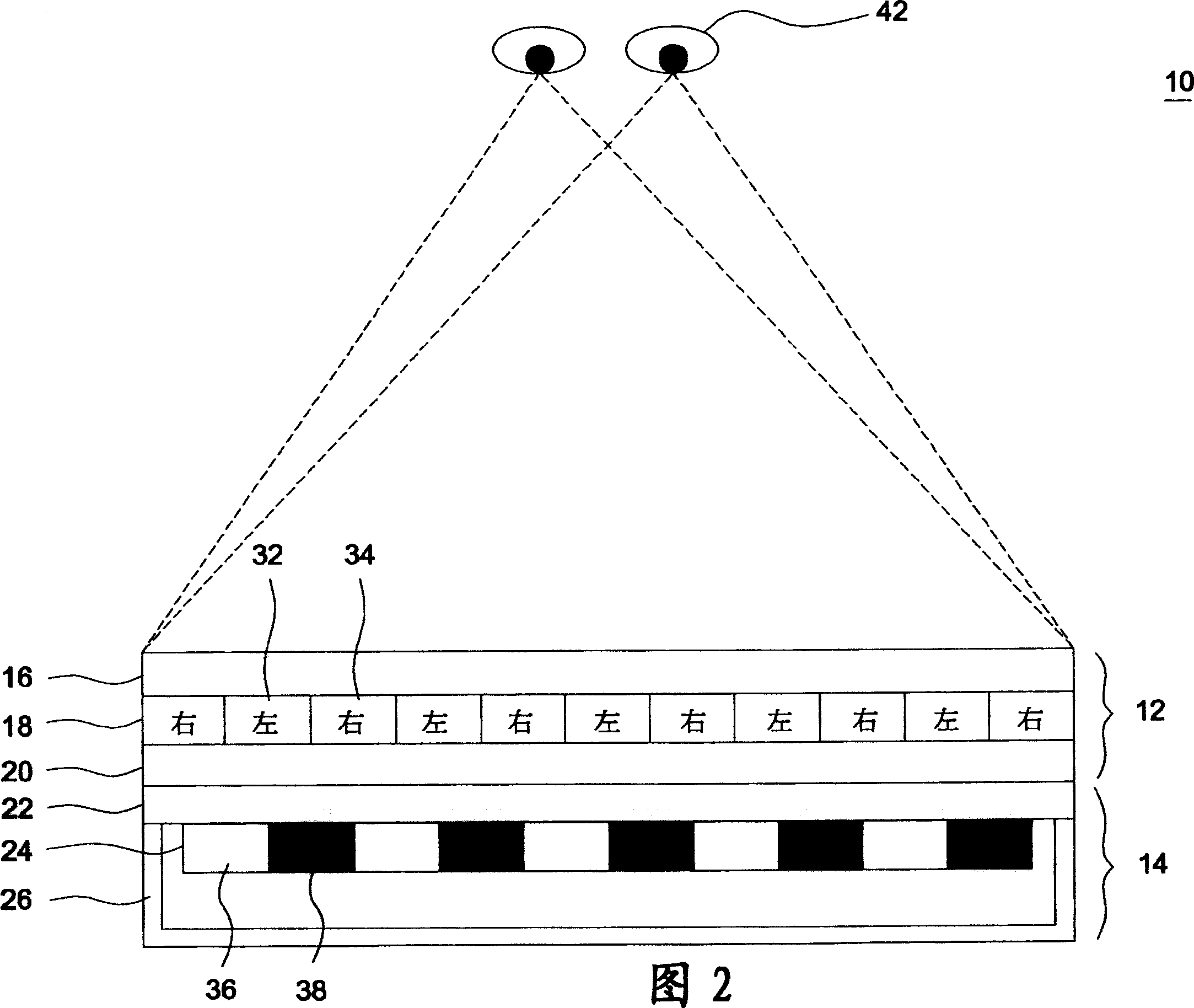
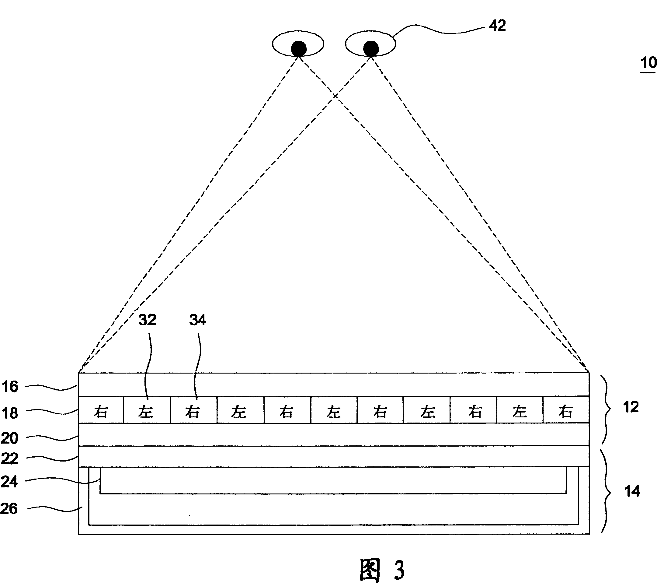
[0041] FIG. 2 is a schematic diagram showing a 2D / 3D image switching display device 10 according to an embodiment of the present invention. As shown in FIG. 2 , the image display device 10 includes a liquid crystal display panel 12 and a light source parallax element 14 . The liquid crystal display panel 12 has transparent substrates 16 and 20, and a liquid crystal layer 18 interposed between the two transparent substrates 16 and 20, and is formed with a plurality of first pixel units 32 and a plurality of pixel units respectively displaying left-eye and right-eye image data. The second pixel unit 34 . The first pixel unit 32 and the second pixel unit 34 are disposed on the liquid crystal display panel 12 in a manner of alternately spaced arrangement.

[0042] According to this embodiment, the light source parallax element 14 is an organic light emitting diode display panel (OLED display), which has a transparent substrate 22 , an organic electroluminescence layer 24 disposed...


PUM


Abstract

The invention is a 2D/3D video switching display unit, comprising a LCD panel and a light-originated parallax component, which has a first mode of forming a complete light emitting region and a second mode of forming multiple interlaced light emitting regions and dark regions, which are staggered with the pixels of the LCD to generate visual separation effect.

Description

technical field [0001] The present invention relates to an image display device, in particular to an image display device with both planar two-dimensional (2D) and stereoscopic three-dimensional (3D) display modes. Background technique [0002] FIG. 1 is a schematic diagram of a known image display device 100 having both planar two-dimensional (2D) and stereoscopic three-dimensional (3D) display modes. As shown in FIG. 1 , the image display device 100 includes a liquid crystal display panel 110 , a liquid crystal shutter (LCD shutter) 120 , and a backlight 130 . The liquid crystal display panel 110 has substrates 111 and 113 , and a liquid crystal layer 112 sealed between the substrates 111 and 113 . The liquid crystal light valve 120 also has substrates 121 and 123 , and a liquid crystal layer 122 sealed between the substrates 121 and 123 . The liquid crystal light valve 120 is used as a parallax element to produce the visual separation effect of the left and right eyes. ...

Claims


Application Information

Patent Timeline
IPC IPC(8): G02B27/22G02F1/133G09F9/00
Inventor 郭建忠
Owner WINTEK CORP
Why Eureka
Try Eureka