
Luminescent device and method for controlling luminescent unit

A light-emitting unit and light-emitting device technology, applied in optics, nonlinear optics, instruments, etc., can solve the problems of complex circuits and high costs

Inactive Publication Date: 2008-01-09
BENQ CORP
View PDF0 Cites 2 Cited by
  • Summary
  • Abstract
  • Description
  • Claims
  • Application Information

AI Technical Summary

Problems solved by technology

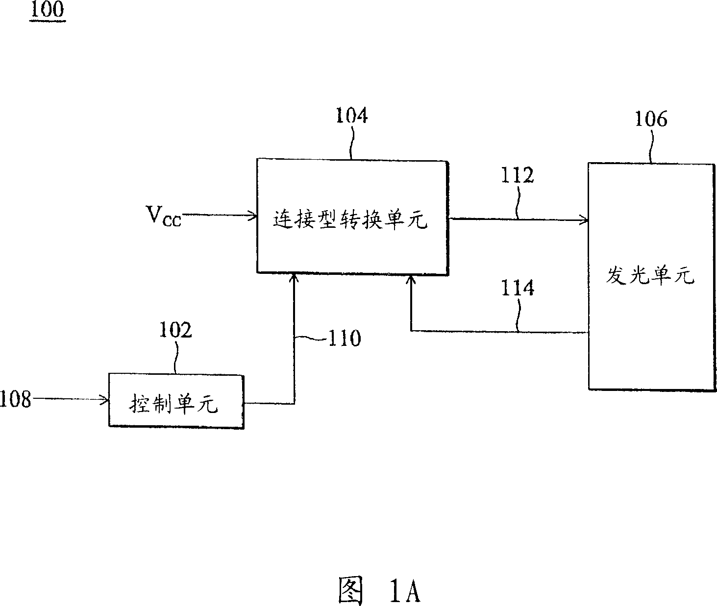
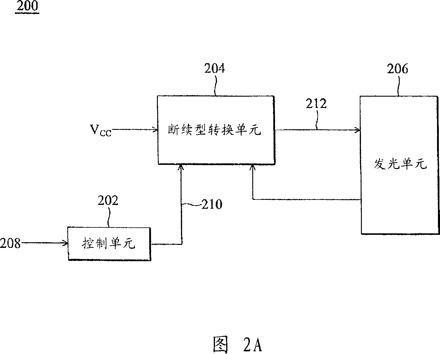
However, the circuit of the discontinuous conversion unit 204 is quite complicated, and the cost is higher than that of the continuous conversion unit 104.

Method used


Image

  • Luminescent device and method for controlling luminescent unit
  • Luminescent device and method for controlling luminescent unit
  • Luminescent device and method for controlling luminescent unit

Examples


Embodiment Construction

[0043] FIG. 3A is a block diagram of a light emitting device 300 of the present invention. In the present invention, the continuous conversion unit 104 is improved according to the requirements of the present invention to form a continuous conversion unit 304 . The continuous conversion unit 304 also has the advantages of simple circuit and low cost. The light emitting device 300 includes a light emitting unit 306 , a control unit 302 , and a continuous conversion unit 304 . The control unit 302 generates a switching unit control signal 310 according to a command signal 308, and the command signal 308 is used to set the target brightness of the light emitting unit. The continuous conversion unit 304 receives a DC voltage Vcc and generates a light emitting unit control signal 312 according to the conversion unit control signal 310 to control the brightness of the light emitting unit. The signal received by the continuous conversion unit 304 can also be a DC current signal. I...


PUM


Abstract

The invention is a light emitter and a method of controlling light emitting cell, when command signal is greater than threshold, conversion cell control signal generated by control cell is a continuous pulse signal, and the stronger the command signal is, the longer the working cycle of the conversion cell control signal is. When the command signal is less than the threshold, the conversion cell control signal is an intermittent pulse signal and the weaker the command signal is, the larger the number of omitted pulses of the conversion cell control signal; when the conversion cell control signal is a continuous pulse signal, the light emitting cell control signal generated by the continuous conversion cell is a continuous AC signal, and the longer the working cycle of the conversion cell control signal, the higher the amplitude of the light emitting cell control signal; when the conversion cell control signal is an intermittent pulse signal, the light emitting cell control signal is an intermittent AC signal, and the larger the number of omitted pulses of the conversion cell control signal, the longer the intermittent time of the light emitting cell control signal. And the light emitting cell control signal will determine brightness of the light emitting cell.

Description

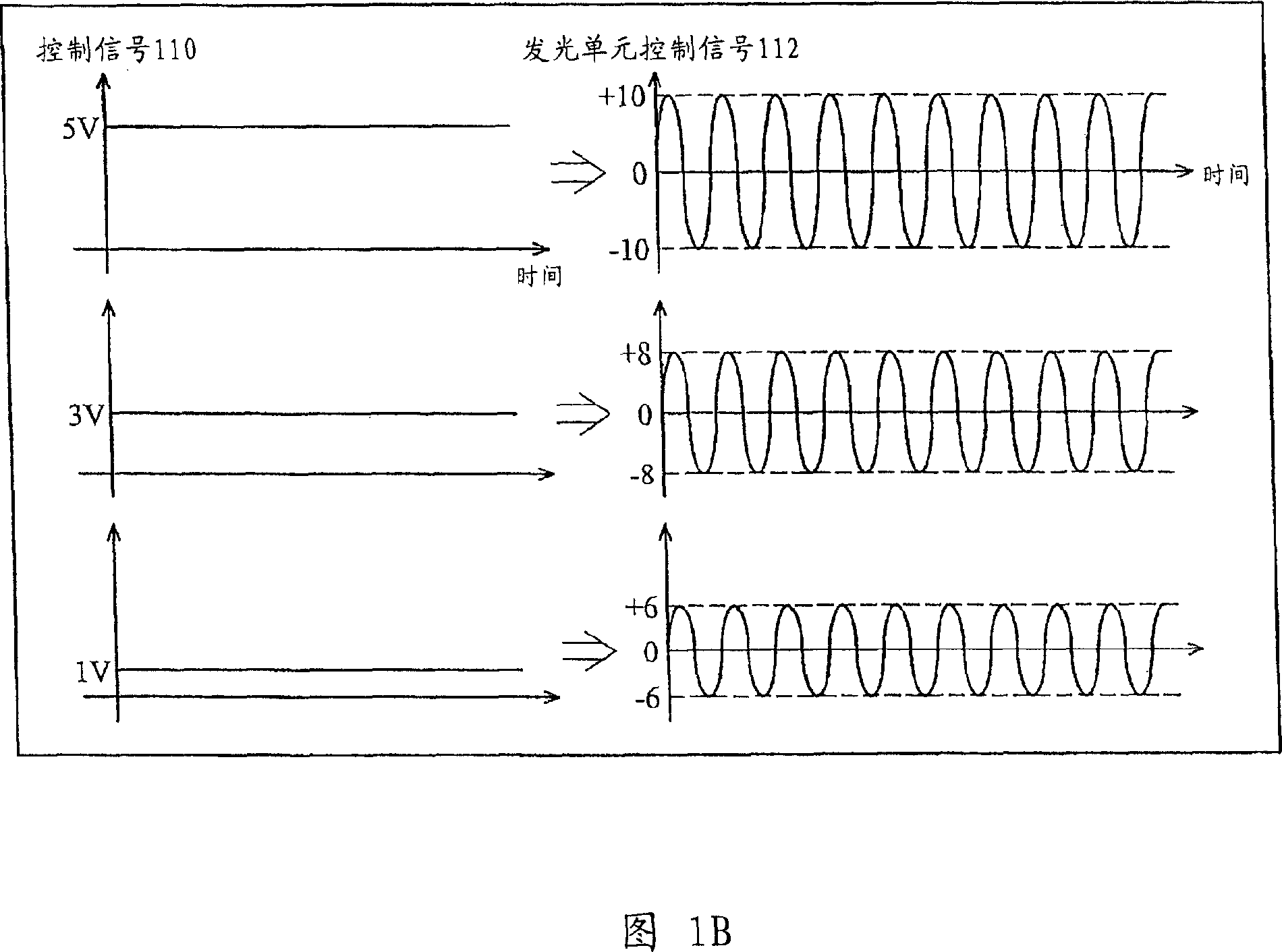
technical field [0001] The present invention relates to a light emitting device, in particular to a device and a method for controlling a light emitting unit of the light emitting device. Background technique [0002] A backlight module is one of the key components of a liquid crystal display panel (LCD panel). Since the liquid crystal itself does not emit light, the function of the backlight module is to provide sufficient brightness and evenly distributed light source so that it can display images normally. [0003] There are two traditional light emitting devices that can be used as a backlight module, one is a continuous mode light emitting device, and the other is a burst mode light emitting device. FIG. 1A is a block diagram of a continuous light emitting device 100 , which includes a control unit 102 , a continuous mode inverter 104 , and a light emitting unit 106 . The control unit 102 generates a control signal 110 according to a command signal 108 . The function...

Claims


Application Information

Patent Timeline
IPC IPC(8): G02F1/13357G09G3/34G02F1/1335
Inventor 郭秉钦许永沂
Owner BENQ CORP
Learn More