
Optical projection apparatus

A technology of optical projection and projection lens, applied in optics, projection devices, instruments, etc., can solve problems such as overheating of projectors, blockage of air outlets and air inlets, etc.

Inactive Publication Date: 2008-01-09
BENQ CORP
View PDF0 Cites 4 Cited by
  • Summary
  • Abstract
  • Description
  • Claims
  • Application Information

AI Technical Summary

Problems solved by technology

However, in the process of operating the projector, users often inadvertently block the air outlet or air inlet
As a result, the cooling fan cannot effectively guide the cooling air into the projector or export the overheated air out of the projector, causing the projector to overheat

Method used


Image

  • Optical projection apparatus
  • Optical projection apparatus

Examples


Embodiment Construction

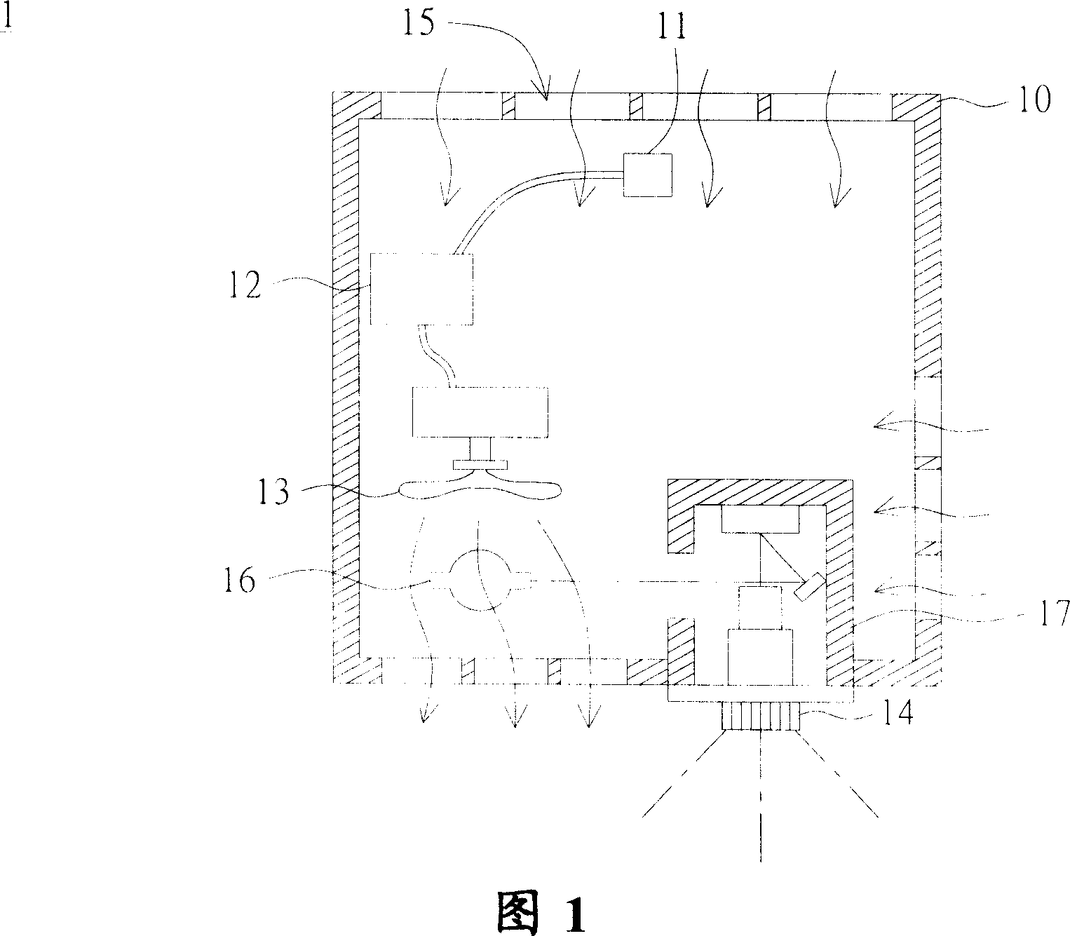
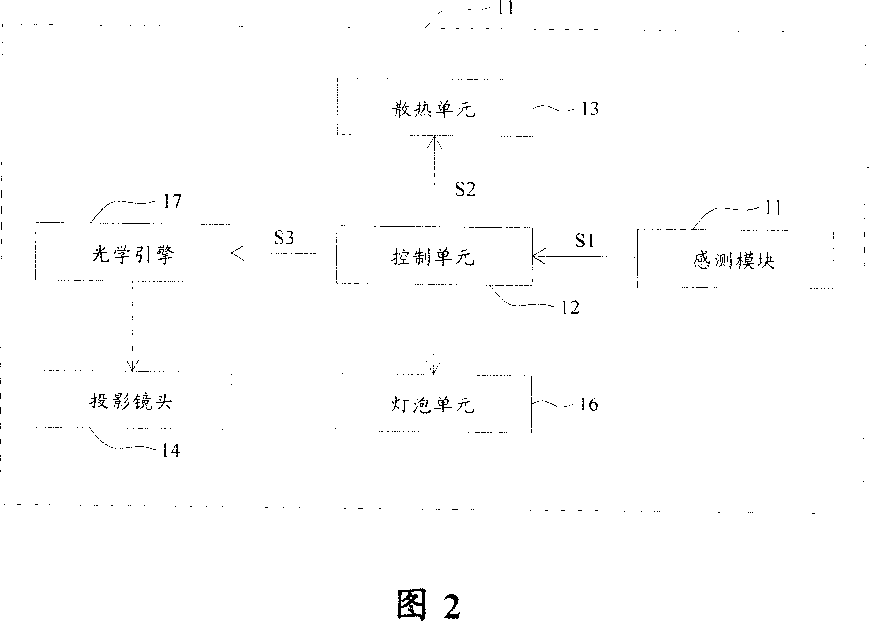
[0010] Please refer to FIG. 1 , which is a schematic diagram of an optical projection device according to a preferred embodiment of the present invention. As shown in FIG. 1 , the optical projection device 1 includes a device body 10 and a sensing module 11 . The device body 10 has a control unit 12 , a cooling unit 13 , a projection lens 14 and at least one air vent 15 . Wherein, the air flow opening 15 may be an air inlet or an air outlet. Certainly, the device body 10 may have both an air inlet and an air outlet. In this embodiment, only the air outlet 15 is shown for illustration.

[0011] The cooling unit 13 is electrically connected to the control unit 12 , and the projection lens 14 is used for projecting images. The hot air flow inside the device body 10 exchanges with the cold air flow outside the device body 10 through the air outlet 15 . The sensing module 11 is disposed in the device body 10 and electrically connected with the control unit 12 . When the sensing...


PUM


Abstract

The invention is an optical projector, comprising main body and sensing module, where the main body has control unit, radiation unit, projection lens and at least an airflow orifice, where the sensing module is arranged in the main body and the sensing module and the radiation unit are connected with the control unit; hot airflow in the main body exchanges with cold airflow outside the main body; when the sensing module detects object enters into a preset range around the airflow orifice, the sensing module will send signal to the control unit to make the control unit start up overheat mechanism.

Description

technical field [0001] The present invention relates to an optical projection device, and in particular to an optical projection device with a sensing module to detect whether the air inlet or outlet of the device is blocked by foreign objects to reduce the heat dissipation effect and activate the anti-overheating mechanism device. Background technique [0002] Whether it is for business or leisure purposes, the main purpose of a projector is to enlarge and project an image onto a screen. The main components of a traditional projector are a projection lens, an optical engine, and a light bulb. After the light emitted by the bulb passes through the optical engine, the image is projected onto the screen by the projection lens. When using a projector, the lamp must be continuously lit, and its luminous intensity must be sufficient to project a magnified image on the screen. As the bulb continues to glow, its heat will continue to increase. At the same time, when the light i...

Claims


Application Information

Patent Timeline
IPC IPC(8): G03B21/16G03B21/00
Inventor 徐子桓
Owner BENQ CORP
Learn More