Unlock instant, AI-driven research and patent intelligence for your innovation.

Television tuner

A technology of TV tuner and capacitor, applied in TV, continuous tuning, color TV and other directions, can solve the problems of increasing cost and no solution, and achieve the effect of reducing the number of parts

Inactive Publication Date: 2008-01-09
SANYO ELECTRIC CO LTD +1
View PDF2 Cites 1 Cited by
  • Summary
  • Abstract
  • Description
  • Claims
  • Application Information

AI Technical Summary

Problems solved by technology

However, since the D / A converter is required in this method, the cost due to the use of the D / A converter increases compared to the cost reduction achieved by sharing the local oscillators for each frequency band. Therefore, did not come up with a practical solution

Method used


Image

  • Television tuner
  • Television tuner
  • Television tuner

Examples


Embodiment 1

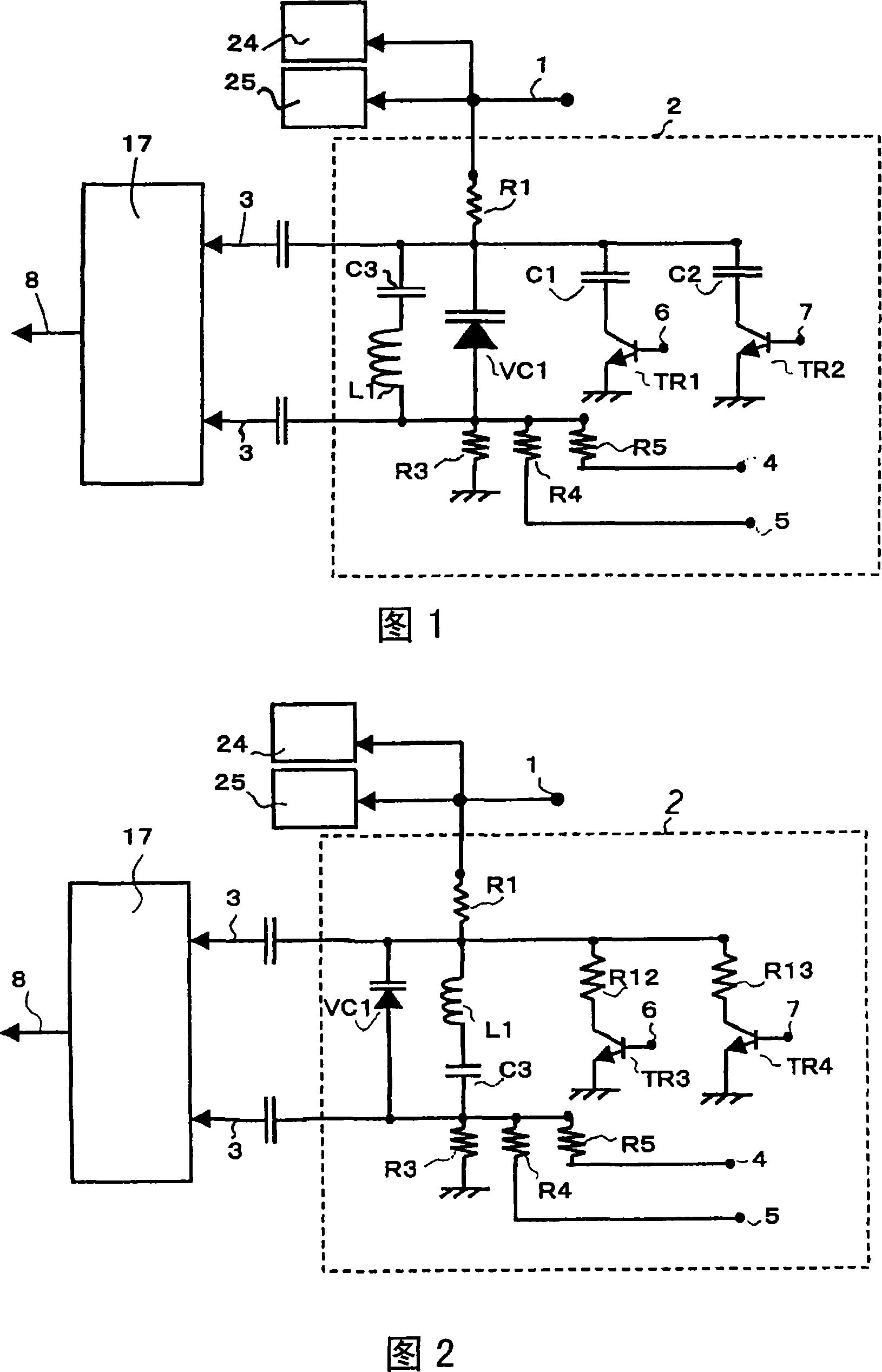
[0047] FIG. 1 is an embodiment of the present invention, and the configuration and operation will be described.

[0048] In the television tuner of the present invention, a resonant circuit 2 for controlling a local oscillation signal 8 is provided for performing desired channel selection. The resonant circuit 2 constitutes an LC resonant circuit formed by a coil L1, a capacitor C3, and a variable capacitance diode VC1, and applies a tuning voltage 1 via a resistor R1. Then, the second correction control signals 4, 5 and the first correction control signals 6, 7 are input to circuit elements R4, R5, C1, TR1, C2, TR2 connected to LC resonant circuits L1, VC1, C3 according to frequency bands. The second correction control signal 4, 5 is applied to lower the reverse potential of the variable capacitance diode VC1, and the first correction control signal 6, 7 makes the capacitors C1, C2 connected in parallel with the resonant circuit 2 operate, thereby making the resonant circuit ...

Embodiment 2

[0053] Fig. 2 shows other embodiments. This embodiment is an embodiment in which the first correction resistor R12 and the second correction resistor R13 are used instead of the first correction capacitor C1 and the second correction capacitor C2 in FIG. 1 . The action during correction is the same as that of the embodiment in FIG. 1 , and the tuning voltage can be divided when the switches TR3 and TR4 operate by setting an appropriate resistance ratio. As a result, the tuning voltage applied to the resonance circuit 2 can be substantially reduced relative to the tuning voltage applied to the frequency selection circuits 24 and 25, and the resonance frequency can be lowered.

Embodiment 3

[0055] 3 to 4 show specific examples. FIG. 3 is a block diagram of the present invention, and FIG. 4 is an embodiment of a circuit using an LSI for a tuner. In FIG. 3 , since the schematic configuration of the tuner from the large line 41 for receiving broadcast waves to the transmission of the intermediate frequency signal 48 and the resonant circuit constituting the local oscillator for UHF are the same as those of the conventional example in FIG. 5 , they are omitted here. its description.

[0056] The difference between FIG. 3 and the conventional example (FIG. 5) is that when receiving a signal other than the first frequency band, the local oscillation signal output from the local oscillator 17 is adjusted so that each frequency band corresponds to a predetermined frequency. 8 for frequency division. For example, the frequency divider 10 divides the local oscillation signal 8 for the UHF band (for example, 1 / 2 times, 1 / 4 times), and uses it as the local oscillation sign...


PUM


Abstract

A correcting circuit, which comprises a capacitor and a switch, is added to a resonator such that a single resonance circuit is used to deal with the television signals of a plurality of bands. Moreover, the number of components of a tuner circuit is reduced. [MEANS FOR SOLVING PROBLEMS] A television tuner receives television broadcast signals, which are divided into a plurality of frequency bands, and converts them to intermediate frequency signals having a predetermined frequency. The television tuner has a resonance circuit (2) that controls the frequency of a local oscillation signal (8) that oscillates within a predetermined frequency band. During reception of a first frequency band, a tuning voltage (1) is applied to a variable circuit element (VC1) in the resonance circuit (2), thereby controlling the frequency of the local oscillation signal (8). During reception of a second frequency band, the tuning voltage (1) is applied to the variable circuit element (VC1) in the resonance circuit (2) and a correction control signal is applied to a fixed circuit element connected to the variable circuit element, thereby controlling the frequency of the local oscillation signal (8).

Description

technical field [0001] The present invention relates to a technique for reducing the size and cost of a TV tuner for receiving TV signals. Background technique [0002] In recent years, digital broadcasting has begun to be used in television broadcasting, and analog broadcasting and digital broadcasting will be used simultaneously before full digitization. [0003] For example, as an example, in the current analog TV signal, for the UHF frequency band (13 to 62 channels, one channel is set every 6 MHz between 470 MHz and 770 MHz in Japan, and one channel is set every 6 MHz between 470 MHz and 890 MHz in the United States. Set a channel, Europe sets a channel every 8MHz between 470MHz~862MHz), VHF-Hi frequency band (4~12 channels, Japan sets a channel every 6MHz between 170MHz~222MHz, and the United States sets a channel between 174MHz~ One channel is set every 6MHz between 216MHz, one channel is set every 7MHz between 174MHz and 230MHz in Europe), VHF-Lo frequency band (1 t...

Claims


Application Information

Patent Timeline
Patent Type & Authority Applications(China)
IPC IPC(8): H04N5/44H04B1/16H04B1/26
CPCH04N5/50H03J3/185H03J5/244
Inventor 大平晃嗣
Owner SANYO ELECTRIC CO LTD