
Oil tray for a combustion engine

A technology of oil collecting device and internal combustion engine, which is applied to the device for keeping the lubricant liquid level constant, the lubrication of the engine, the oil pan, etc., which can solve the problems of troublesome installation and complicated structure, and achieve simple structure, simple installation and low cost. cost effect

Inactive Publication Date: 2008-01-16
DR ING H C F PORSCHE AG
View PDF3 Cites 5 Cited by
  • Summary
  • Abstract
  • Description
  • Claims
  • Application Information

AI Technical Summary

Problems solved by technology

Although the known oil collecting devices meet this purpose, these devices have a relatively complicated structure, which also requires complicated installation.
A further disadvantage is that both tank sections always have to be emptied separately for an oil change, which is also labor-intensive

Method used


Image

  • Oil tray for a combustion engine
  • Oil tray for a combustion engine
  • Oil tray for a combustion engine

Examples


Embodiment Construction

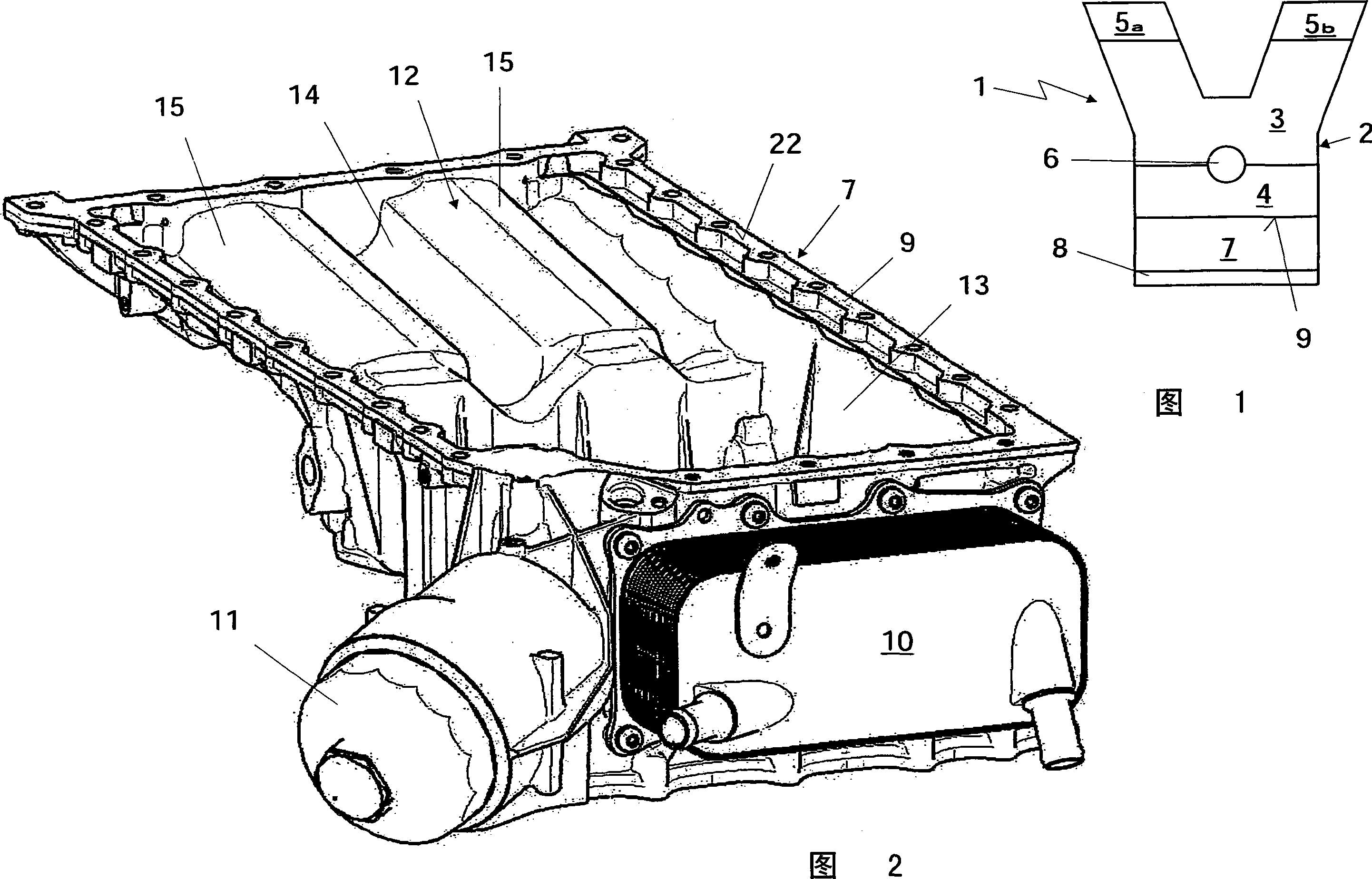
[0019] FIG. 1 is a schematic illustration of an internal combustion engine 1 with a crankcase 2 . The crankcase has a crankcase upper part 3 and a crankcase lower part 4 , also called bedplate. Two cylinder heads 5 a and 5 b are arranged on the crankcase 2 , which in this case is designed in a V-shaped configuration. The two cylinder heads can be designed in a design known per se. A crankshaft 6 is also rotatably mounted between the upper crankcase part 3 and the lower crankcase part 4 in a manner known per se. In addition, an oil collection tank 7 connected to the lower part 4 of the crankcase is also provided at the lower part of the crankcase 2 . The oil collecting tank is also designed in a manner known per se to hold lubricating oil for the internal combustion engine and is closed downwards by an oil sump 8 . The oil sump 8 can be made of sheet metal, for example in the form of a cover, and is necessary because the oil collecting tank 7 is in this case a die-cast part ...


PUM


Abstract

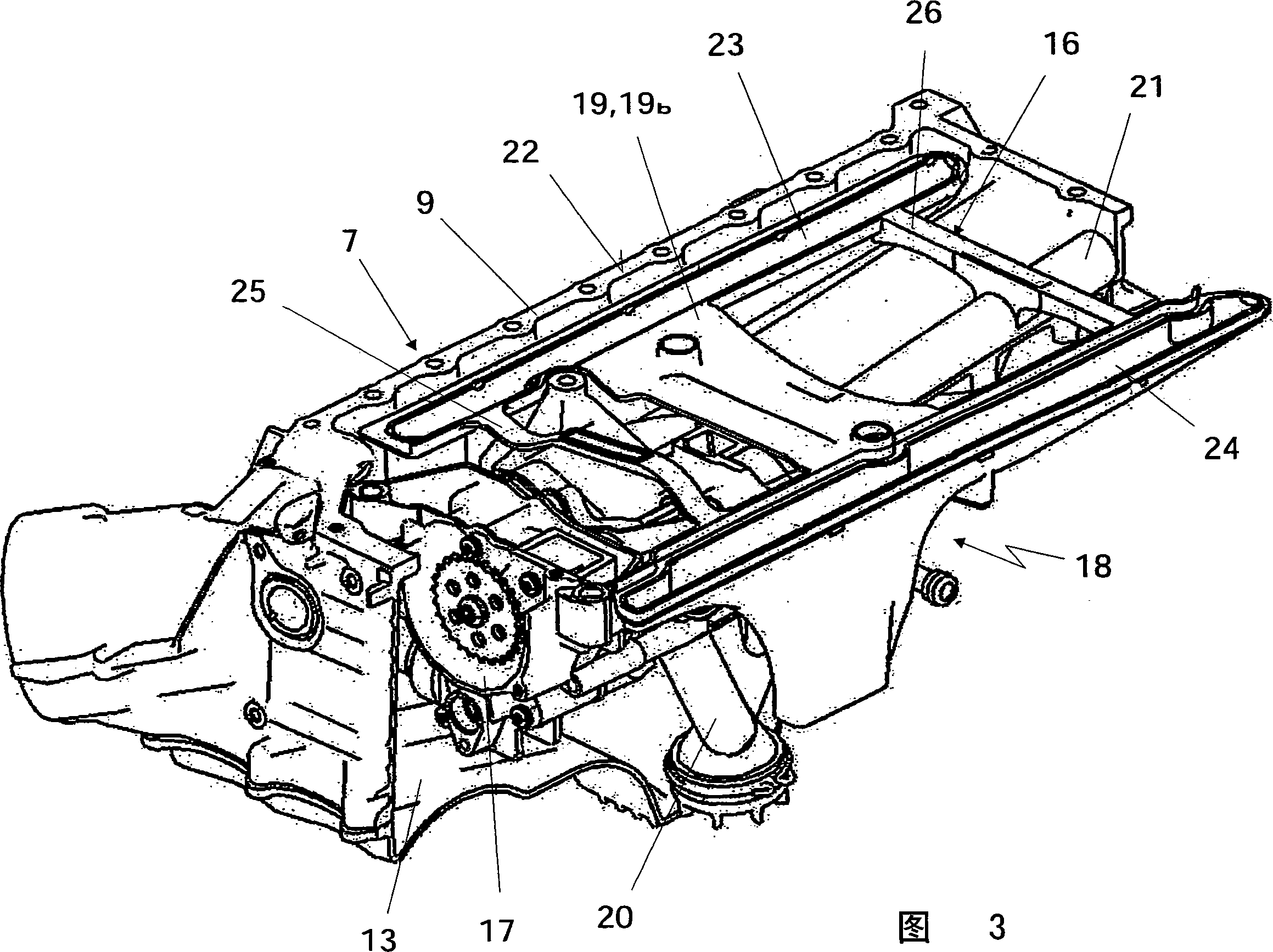
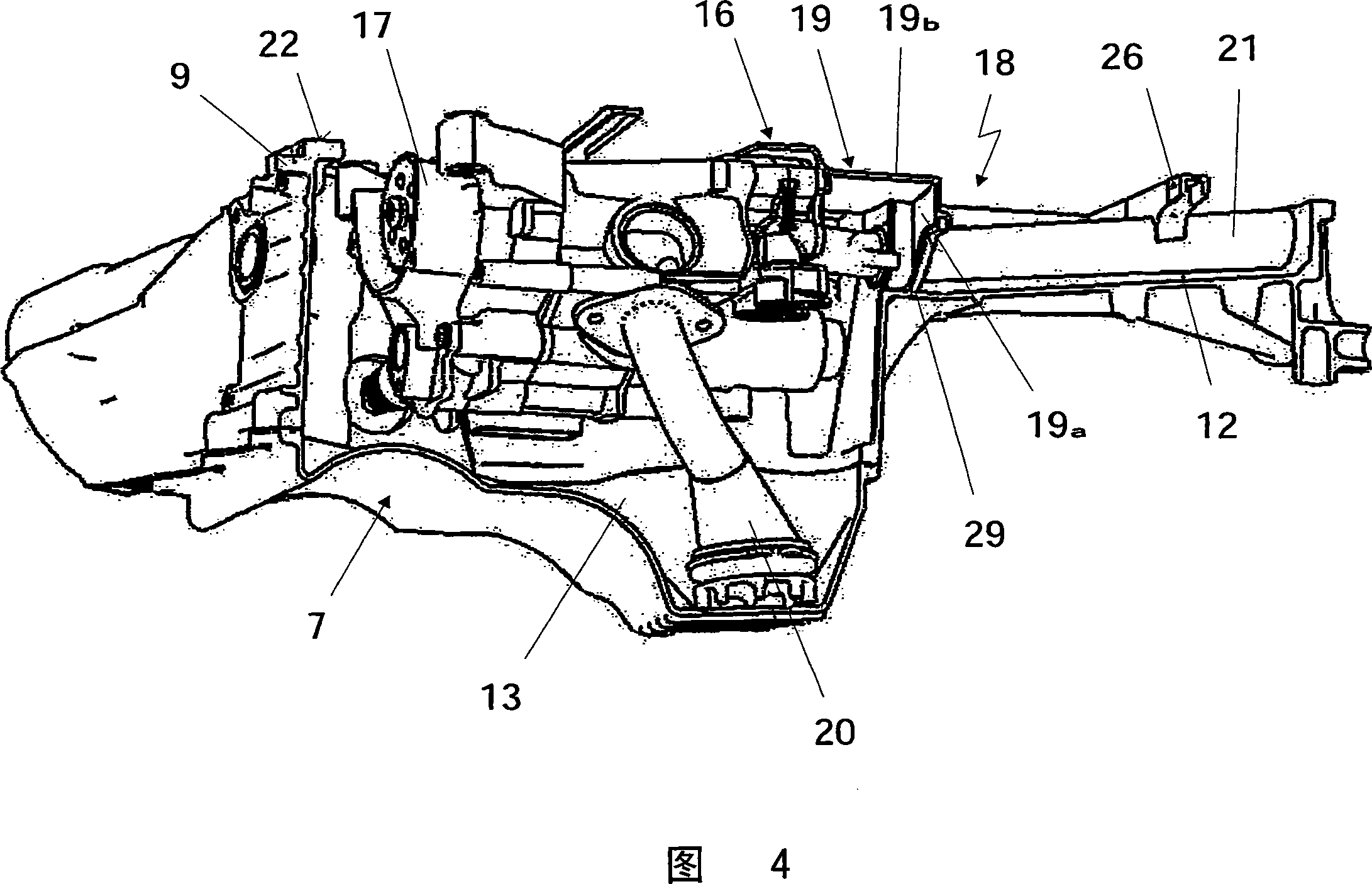
The present invention relates to an oil gathering device (18) for the internal combustion engine (1) which is provided with an oil gathering tank (7) arranged at the lower part of the crankcase (2), the oil gathering tank is provided with the following components: at least two box body sections and the structure space depths of which are different, an oil pump (17) which draws engine oil from at least two casing section (12, 13), at least two oil drawing pipes (20, 21) from the oil pump to at least two box body sections, and an inserted component (16) provided with at least one partition board which is used to separate the two box body sections. The flat oil drawing pipe (21) of the box body section (12) to the oil gathering tank (7) is composed to the inserted component (16) integrated. One simplified structure of the oil gathering device is produced by the measures. In the structure the oil gathering device guarantees that the installing of the inserted components in the oil gathering tank are simple and the structural elements and cost are reduced.

Description

technical field [0001] The invention relates to an oil collecting device for an internal combustion engine of the type defined in detail in the preamble of claim 1 with an oil collecting tank arranged in the lower part of the crankcase. Background technique [0002] DE 101 05 435 A1 describes an oil collecting device of this type. DE 101 59 090 C2 and DE 101 59 014 B4 also disclose similar devices or internal combustion engines equipped with such devices. In order to ensure an oil supply to the internal combustion engine even in extreme driving situations, two suction lines, also called suction stages, to the oil pumps of at least two housing sections with different installation space depths are required of. Although the known oil collecting devices fulfill this purpose, they have a relatively complex structure which, moreover, requires complex installation. A further disadvantage is that both tank sections always have to be emptied separately for an oil change, which is ...

Claims


Application Information

Patent Timeline
IPC IPC(8): F01M11/00F01M11/06F01M1/02
CPCF01M2011/0033F01M2011/0037F01M2011/0025F01M11/0004F01M2011/007F01M2011/0029
Inventor N·沃克尔
Owner DR ING H C F PORSCHE AG
Learn More