Motorcycle engine vibration damping device

A vibration damping mechanism and engine technology, which is applied in the direction of engine components, machines/engines, mechanical equipment, etc., can solve the problems of inability to reduce vibration, crankcase cannot be installed, cost increase, etc., to improve output power and torque, The effect of improving user comfort and reducing production costs

Inactive Publication Date: 2010-12-08
力帆科技(集团)股份有限公司
View PDF6 Cites 3 Cited by
  • Summary
  • Abstract
  • Description
  • Claims
  • Application Information

AI Technical Summary

Problems solved by technology

[0003] For large-displacement motorcycle engines, due to the increase in displacement, the rotational inertial force and reciprocating inertial force generated by the movement of the moving parts of the engine (crank-link mechanism) also increase accordingly. If the shaft balance mechanism cannot completely balance the first-order reciprocating inertial force, the purpose of reducing vibration cannot be achieved
[0004] Some large-displacement motorcycle engines use a biaxial balance mechanism to balance the reciprocating inertial force generated during the operation of the crank-link mechanism (the balance method of the rotational inertia force is the same as that of the uniaxial balance mechanism), and the biaxial balance mechanism has a complex structure and a large volume. , the original crankcase cannot be installed, and the crankcase still has to be molded again, which leads to an increase in cost. The price of the complete motorcycle is expensive, and it is difficult for users to accept it.

Method used


Image

  • Motorcycle engine vibration damping device
  • Motorcycle engine vibration damping device
  • Motorcycle engine vibration damping device

Examples


Embodiment Construction

[0017] Below in conjunction with accompanying drawing and embodiment, the present invention will be further described:

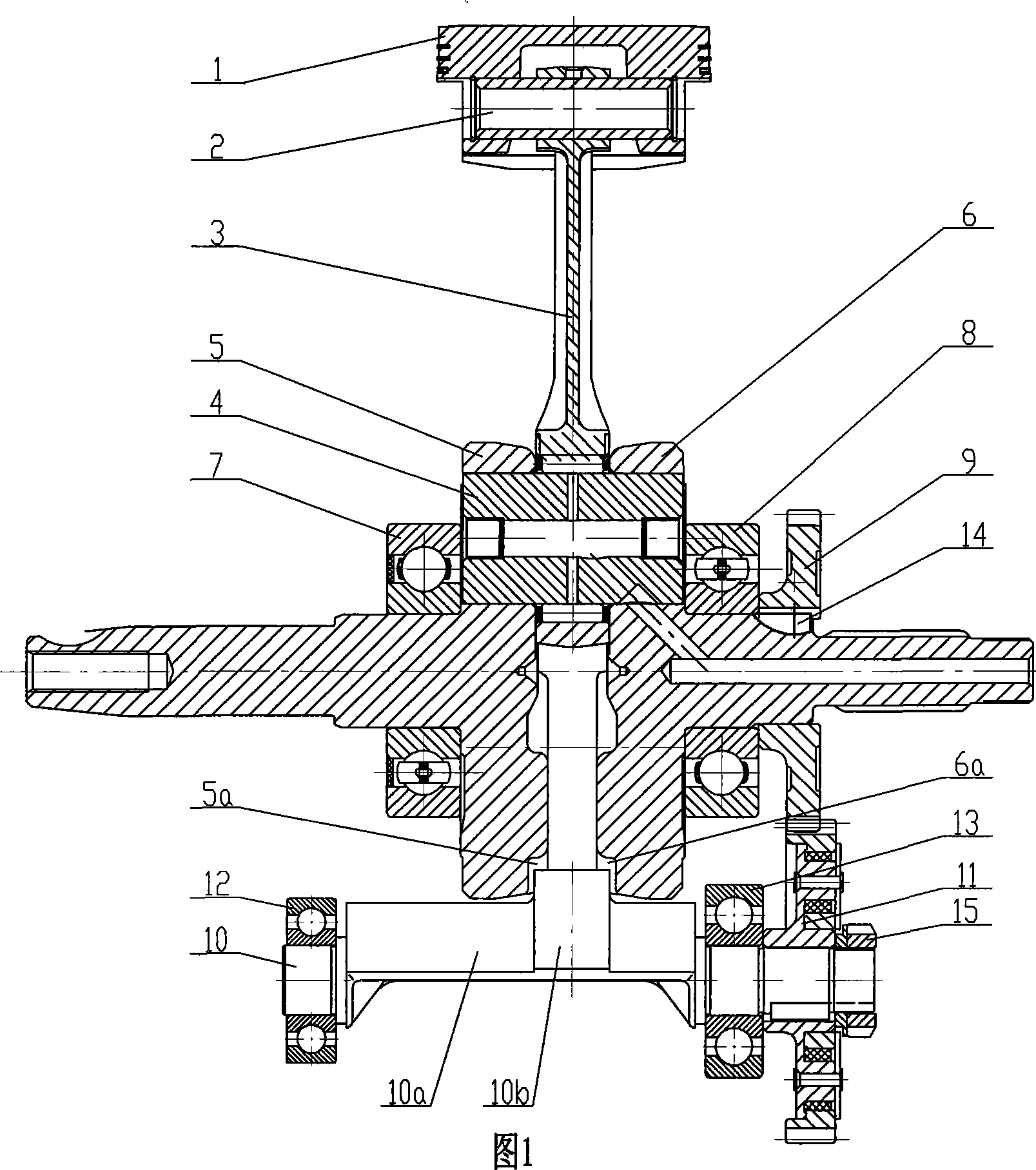
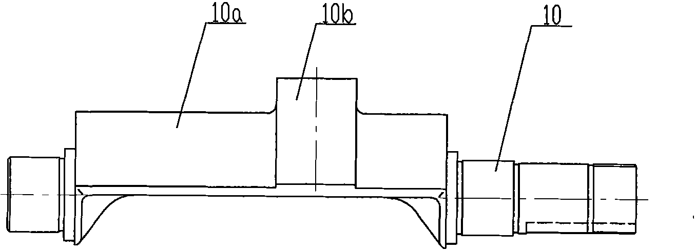
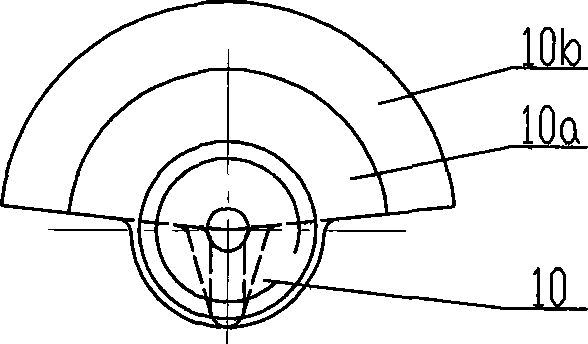
[0018] like figure 1 , Figure 4 and Figure 5 As shown, in order to reduce the weight of the piston 1 and reduce the reciprocating inertial force during the operation of the crank connecting rod mechanism, the section of the piston 1 along its axis is in a "T" shape. The piston 1 is connected with the small end of the connecting rod 3 through the piston pin 2 , and the large end of the connecting rod 3 is installed between the symmetrically arranged left and right cranks 5 and 6 through the crank pin 4 . Said left and right cranks 5 and 6 are symmetrically provided with notches 5a and 6a on the opposite sides of the handles, wherein the notches 5a on the left crank 5 are arc-shaped and are distributed along the edge of the lower half of the handle of the left crank 5 (see figure 1 and Figure 4 ); the notch 6a on the right crank 6 is also arc-shaped, di...


PUM


Abstract

A vibration damping structure for motorcycle engine is provided. A piston is connected with a small end of a connecting rod through a piston pin, the big end of the connecting rod is arranged between a left crank and a right crank through a crack pin, a left crack shaft bearing is arranged on the left crank, a right crank shaft bearing and a balancing driving gear are sequentially arranged on theright crank, the balancing driving gear is engaged with an balancing driven gear disposed at the right end of a balancing shaft, a second balancing block is equipped in the middle (deviation to the right) position of a first balancing block, the opposite faces of the shank portion of the left and right crank are symmetrically opened with two notches, and when the balancing shaft rotates, the second balancing block can pass through between the two notches of the shank portion of the left and right crank. The invention can effectively balance the reciprocating inertial force generated when the large-discharge amount motorcycle engine running, so as to essentially improve the engine vibration, improve the usage comfort, service life and reliability of the motorcycle. The invention can be arranged with no need to change the structure of crank shaft case, so as to effectively reduce the manufacturing cost of the entire motorcycle.

Description

technical field [0001] The invention belongs to the technical field of motorcycle engines, and in particular relates to a vibration damping mechanism for motorcycle engines. Background technique [0002] At present, in order to solve the problem of large vibration of motorcycle engines, a dual-axis balance mechanism or a single-axis balance mechanism is generally used on the motorcycle engine to balance the reciprocating inertial force generated by the operation of the crank connecting rod mechanism, so as to reduce the impact of engine vibration on motorcycles. The influence of the whole vehicle ensures the comfort of driving and riding. The single-axis balance mechanism often adopts the following structure: the piston is connected to the small end of the connecting rod through the piston pin, the large end of the connecting rod is installed between the left and right cranks through the crank pin, the left crankshaft bearing is assembled on the left crank, and the right cra...

Claims


Application Information

Patent Timeline
Patent Type & Authority Patents(China)
IPC IPC(8): F16F15/26F02F3/00
Inventor 李豫玲尤越
Owner 力帆科技(集团)股份有限公司
Why Eureka
Try Eureka