Evaporator and cabinet type air conditioner indoor machine employing same

A cabinet-type air conditioner and evaporator technology, applied in evaporator/condenser, air conditioning system, application, etc., can solve the problem of high cost of evaporator and achieve the effect of uniform heat exchange

Inactive Publication Date: 2008-01-16
HISENSE +1
View PDF0 Cites 14 Cited by
  • Summary
  • Abstract
  • Description
  • Claims
  • Application Information

AI Technical Summary

Problems solved by technology

[0004] The invention provides an evaporator and a cabinet-type air conditioner indoor unit using the evaporator, wh

Method used


Image

  • Evaporator and cabinet type air conditioner indoor machine employing same

Examples


Embodiment 1

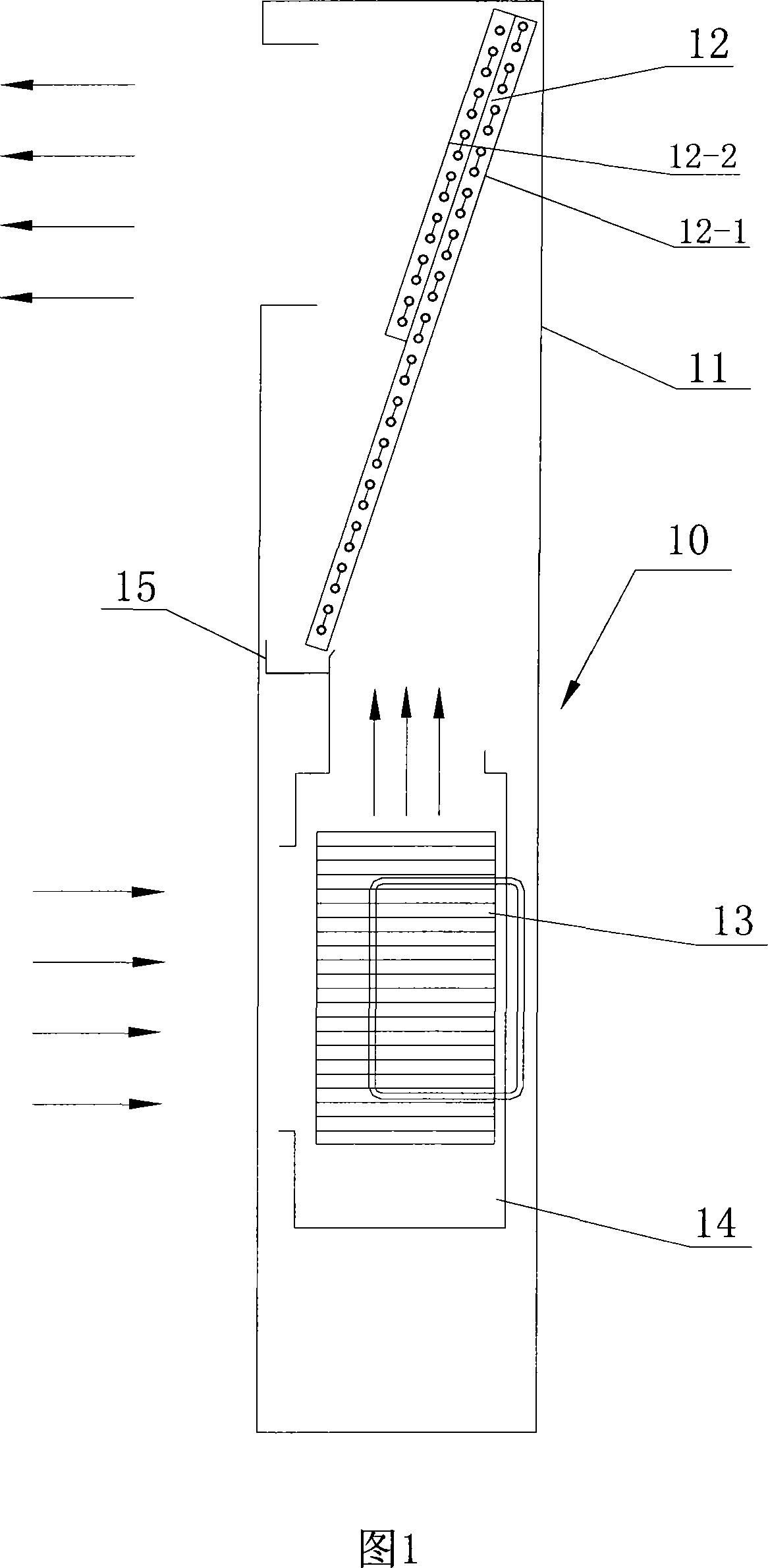
[0016] Embodiment 1, referring to Fig. 1 , an indoor unit 10 of a blower-type cabinet air conditioner includes an indoor unit casing 11, a centrifugal fan volute 14 is installed in the lower casing of the indoor unit, and a centrifugal fan volute 14 is installed in the centrifugal fan volute 14. The centrifugal fan 13 is equipped with an evaporator 12 above the centrifugal fan, which includes a windward side evaporator 12-1 and a leeward side evaporator 12-2, and a water receiving tray 15 at the lower end of the evaporator 12.

[0017] After the external wind enters the interior of the indoor unit casing, it blows to the evaporator 12 through the centrifugal fan 13. The evaporators 12-1 on the windward side form a whole row, and the evaporators 12-2 on the leeward side are arranged on the upper part of the evaporator 12, and its height is Half of the windward side evaporator 12-1. This makes the upper part of the evaporator 12 a double row, and the lower part of the evaporator...


PUM


Abstract

The invention provides an evaporator and a cabinet air conditioner indoor unit equipped with the evaporator. Aiming at the wind field characteristics of the evaporator of blast type cabinet air conditioner, the invention improves the structure of evaporator of indoor unit. The lower part of the evaporator that has poor heat exchange adopts single-row evaporator design, and the upper part of the evaporator hat has sufficient heat exchange adopts double-row evaporator design. Thus, the heat exchange capability of each part of the evaporator can be fully utilized, so that all parts of the evaporator have uniform heat exchange, either assuring the heat exchange performance of the cabinet air conditioner or reducing cost. The invention has good heat exchange performance when being applied to the blast type conditioner indoor unit.

Description

technical field [0001] The invention belongs to the technical field of air-conditioning and refrigeration engineering, in particular to an evaporator and a cabinet-type air-conditioning indoor unit using the evaporation factor. Background technique [0002] At present, the air supply form of the indoor unit of the cabinet type air conditioner generally adopts the blowing method, the evaporator is arranged obliquely on the upper part of the indoor unit, and the centrifugal fan is arranged on the lower part, and the centrifugal fan blows air upward from the bottom. Existing cabinet indoor unit evaporators are generally double-row equal-height flat-plate evaporators, which include a row of evaporators on the windward side and a row of evaporators on the leeward side overlapped. , the lower wind speed and other reasons, in the upward air supply process, the air volume received by the upper part of the evaporator is large, while the air volume received by the lower part is small,...

Claims


Application Information

Patent Timeline
IPC IPC(8): F25B39/02F24F1/00
Inventor 王剑锋陈凤坡
Owner HISENSE
Why Eureka
Try Eureka