
Sintering machine wind box end sealing apparatus

A technology of end sealing and sintering machine, which is applied in the direction of engine sealing, mechanical equipment, engine components, etc. It can solve the bad influence of the sealing effect of the end sealing device of the sintering machine bellows, the top sealing plate cannot be reset in time, and the sealing effect is affected, etc. problems, achieve the effects of preventing jamming, simplifying the structure, and improving the sealing effect

Active Publication Date: 2008-01-16
ZHONGYE-CHANGTIAN INT ENG CO LTD
View PDF0 Cites 5 Cited by
  • Summary
  • Abstract
  • Description
  • Claims
  • Application Information

AI Technical Summary

Problems solved by technology

However, since a certain gap must be reserved between each sealing plate, the existence of the gap will inevitably cause leakage between the bottom beam of the trolley and the sealing plate, which will adversely affect the sealing effect of the sealing device at the end of the bellows of the sintering machine and the sintering ash on the sintering machine trolley is easy to fall from the gap, so the sealing device at the end of the bellows of the sintering machine must have an ash box, which makes the overall structure complicated; in the existing connecting rod mechanism, the middle part of the connecting rod The semi-inner surface of the top sealing plate is in contact with the outer surface of the support rod, and the semi-inner surface of the lower part of the top sealing plate is in contact with the outer surface of the upper end of the connecting rod. Both contacts have a large contact area, and the rotation resistance is relatively large. The phenomenon of jamming occurs, causing the top sealing plate to be pressed down and cannot be reset in time, which affects the sealing effect

Method used


Image

  • Sintering machine wind box end sealing apparatus
  • Sintering machine wind box end sealing apparatus
  • Sintering machine wind box end sealing apparatus

Examples


Embodiment Construction

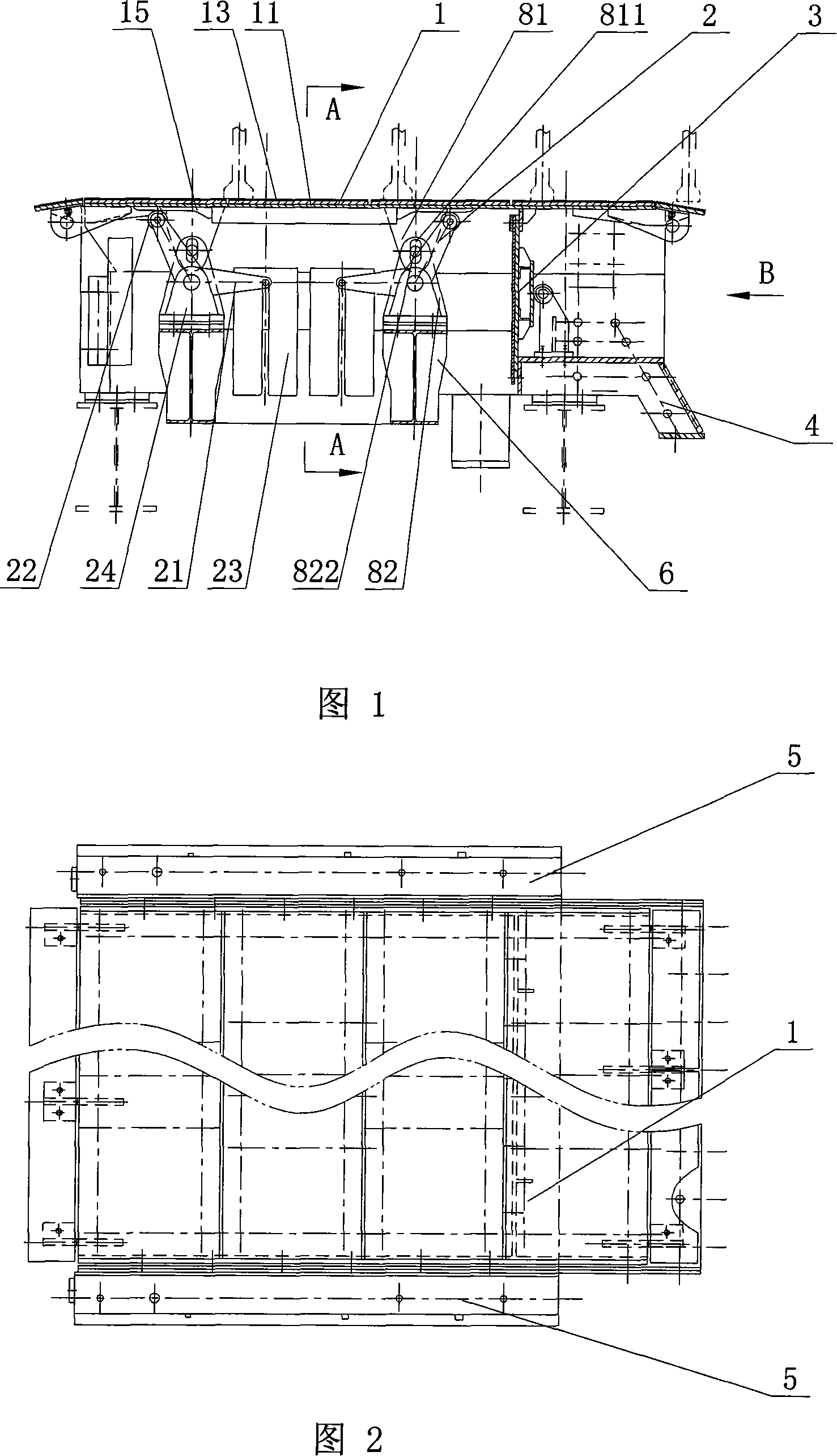
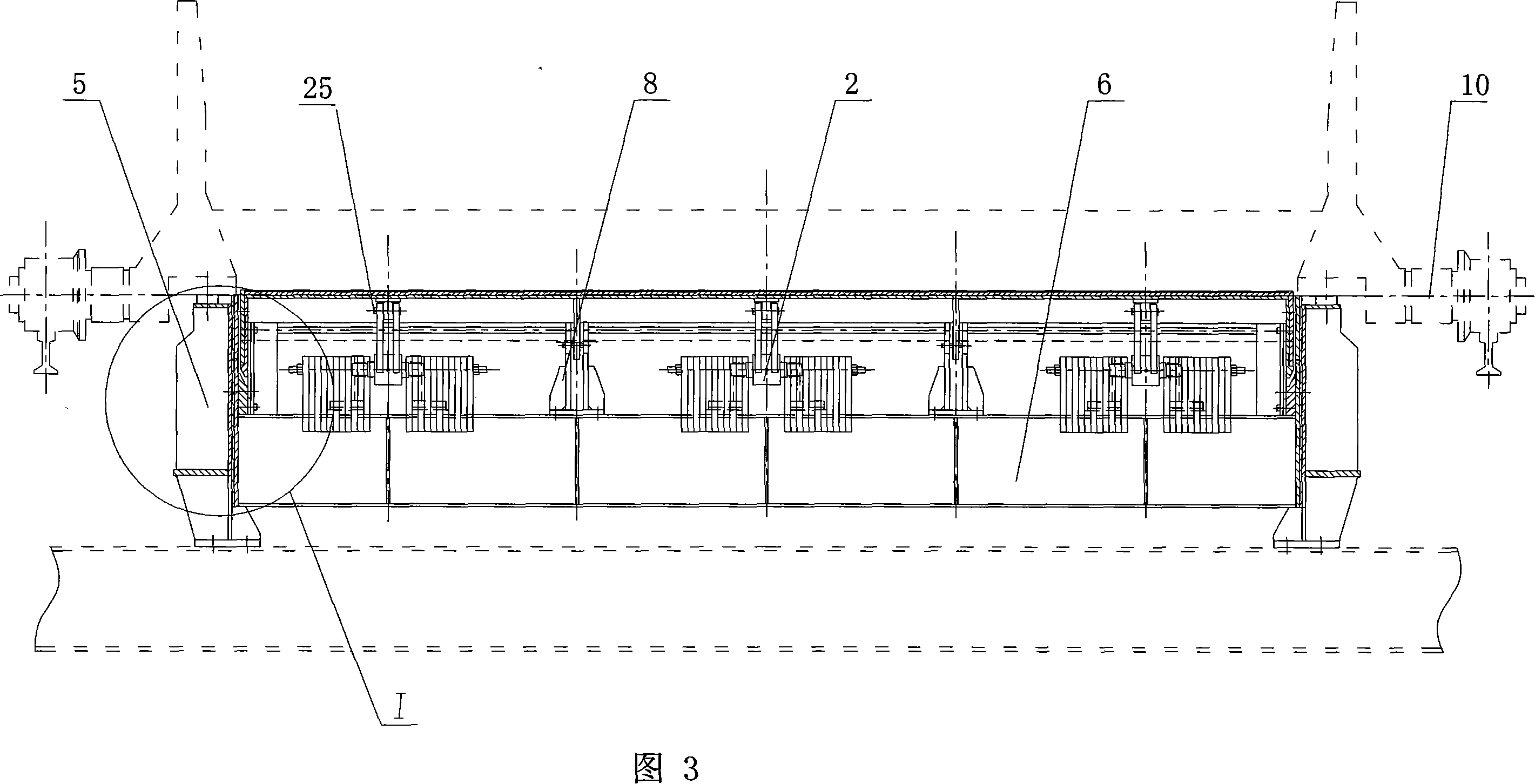
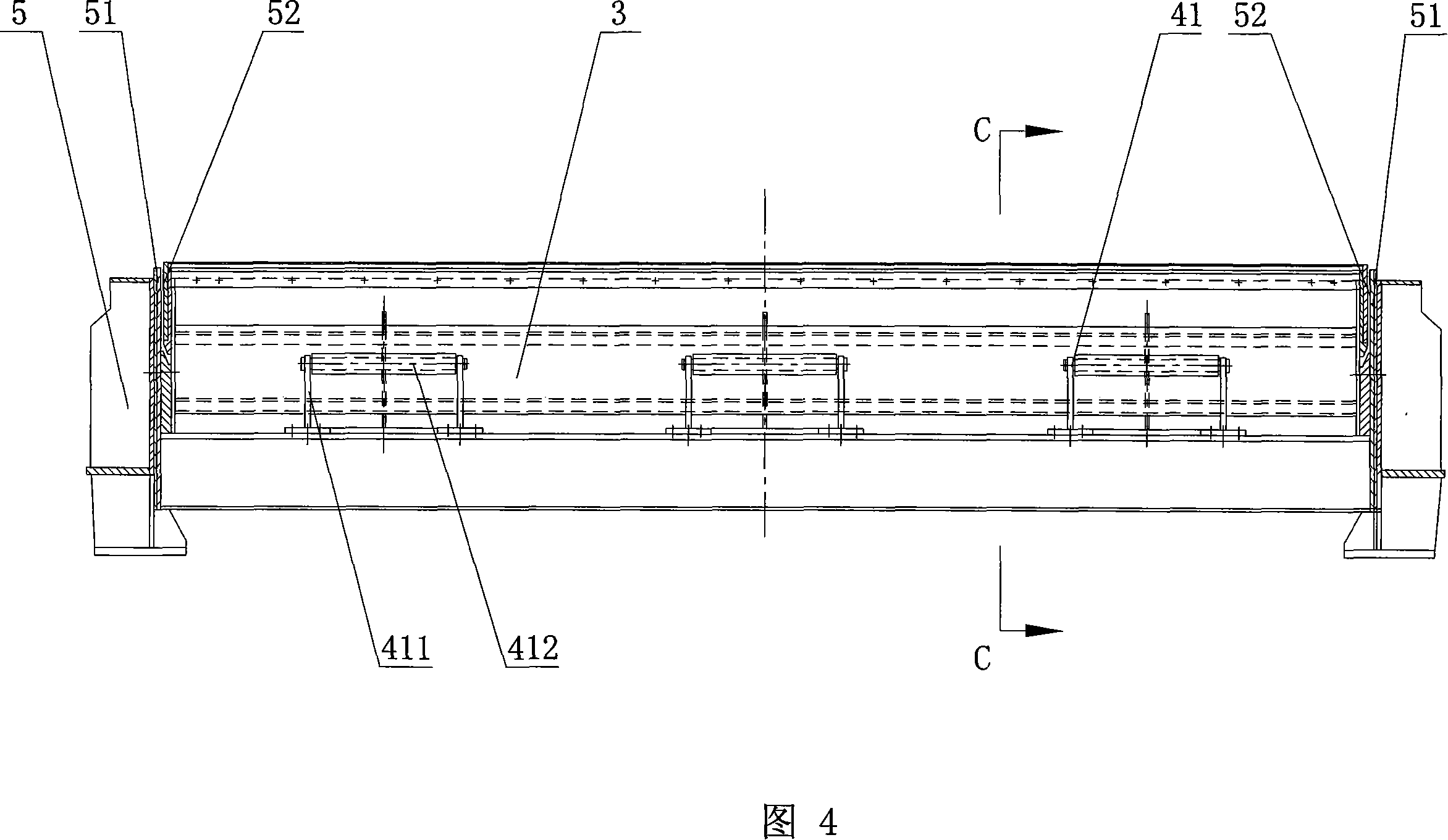
[0042]As shown in Figures 1 to 7, the end sealing device of the sintering machine bellows of the present invention includes a top sealing plate 1, a connecting rod mechanism 2, an end sealing plate 3, a beam frame 4, two side beams 5 and two supporting beams 6 , the two ends of the crossbeam frame 4 and each support beam 6 are respectively connected to the two side beams 5, the crossbeam frame 4 is located in the bellows area, the two support beams 6 are located in the atmospheric pressure area, and each support beam 6 is fixedly equipped with three sets of linkage mechanisms 2, the top The sealing plate 1 is connected above the connecting rod mechanism 2, the upper part of the end sealing plate 3 is connected with the top sealing plate 1, and the lower part is in contact with the beam frame 4, and the top sealing plate 1 is a groove that is set on the inner side of the beams 5 on both sides and opens downward. body, the tank body is composed of elastic whole plate 11 and side ...


PUM


Abstract

The invention discloses an end sealing device for air box of sintering machine, which comprise a top sealing plate, a link mechanism, an end sealing plate, a crossbeam frame, two side beams, and two bearing beams, wherein the crossbeam frame and two ends of each bearing beam are respectively connected with the two side beams, the link mechanism is fixed on the bearing beam, the top sealing plate is connected at the upper place of the link mechanism, the upper part of the end sealing plate is connected with the top sealing plate, the upper part of the end sealing plate contacts with the crossbeam frame, the top sealing plate is a trough sheathed at the inner sides of the two side beams and having a downward opening, the trough is composed of an elastic whole plate and two side plates disposed at two sides of the elastic whole plate, a top lining plate is provided at the top of the elastic whole plate, and two side lining plate is disposed at the outer sides of the two side plates. The end sealing device for air box of sintering machine has the advantages of good sealing effect, long service life, simple structure, and convenient preparation.

Description

technical field [0001] The invention relates to the field of sintering machine equipment, in particular to a sealing device for the end of a sintering machine bellows. Background technique [0002] At present, the bellows of the existing sintering machine are installed under the trolley of the sintering machine. The trolley of the sintering machine is filled with the mixed material and then runs on the track of the trolley. The top of the mixed material is ignited by the ignition furnace, and the bellows draw air from the lower part of the trolley, so that The mixture is sintered downward from the top of the sintering machine trolley. In order to make the bellows achieve a good air extraction effect, it is necessary to ensure a reliable seal between the sintering machine bellows and the sintering machine trolley, so that no air leakage or as little air leakage as possible . The side beams on both sides of the bellows are sealed with the sintering machine trolley, and the en...

Claims


Application Information

Patent Timeline
IPC IPC(8): F27B21/08F16J15/06
Inventor 周胜良刘相佩戴传德王丽娟叶恒棣
Owner ZHONGYE-CHANGTIAN INT ENG CO LTD
Learn More