Driving support method and apparatus

A driving support and driver technology, applied in signal devices, optical observation devices, transportation and packaging, etc., can solve problems such as inability to display the sides of obstacles, loss of continuity, inability to display obstacles, etc.

Inactive Publication Date: 2008-01-16
AISIN AW CO LTD
View PDF1 Cites 12 Cited by
  • Summary
  • Abstract
  • Description
  • Claims
  • Application Information

AI Technical Summary

Problems solved by technology

In the image processing of the above-mentioned device, since only two-dimensional coordinate conversion can be performed, obstacles not captured by the camera cannot be displayed, or the sides of obstacles not captured by the camera cannot be displayed
As a result, there may be a significant loss of continuity between the background image displayed on the front pillars and the background seen through the front and door windows when the driver is in a posture other than the standard one

Method used


Image

  • Driving support method and apparatus
  • Driving support method and apparatus
  • Driving support method and apparatus

Examples


Embodiment Construction

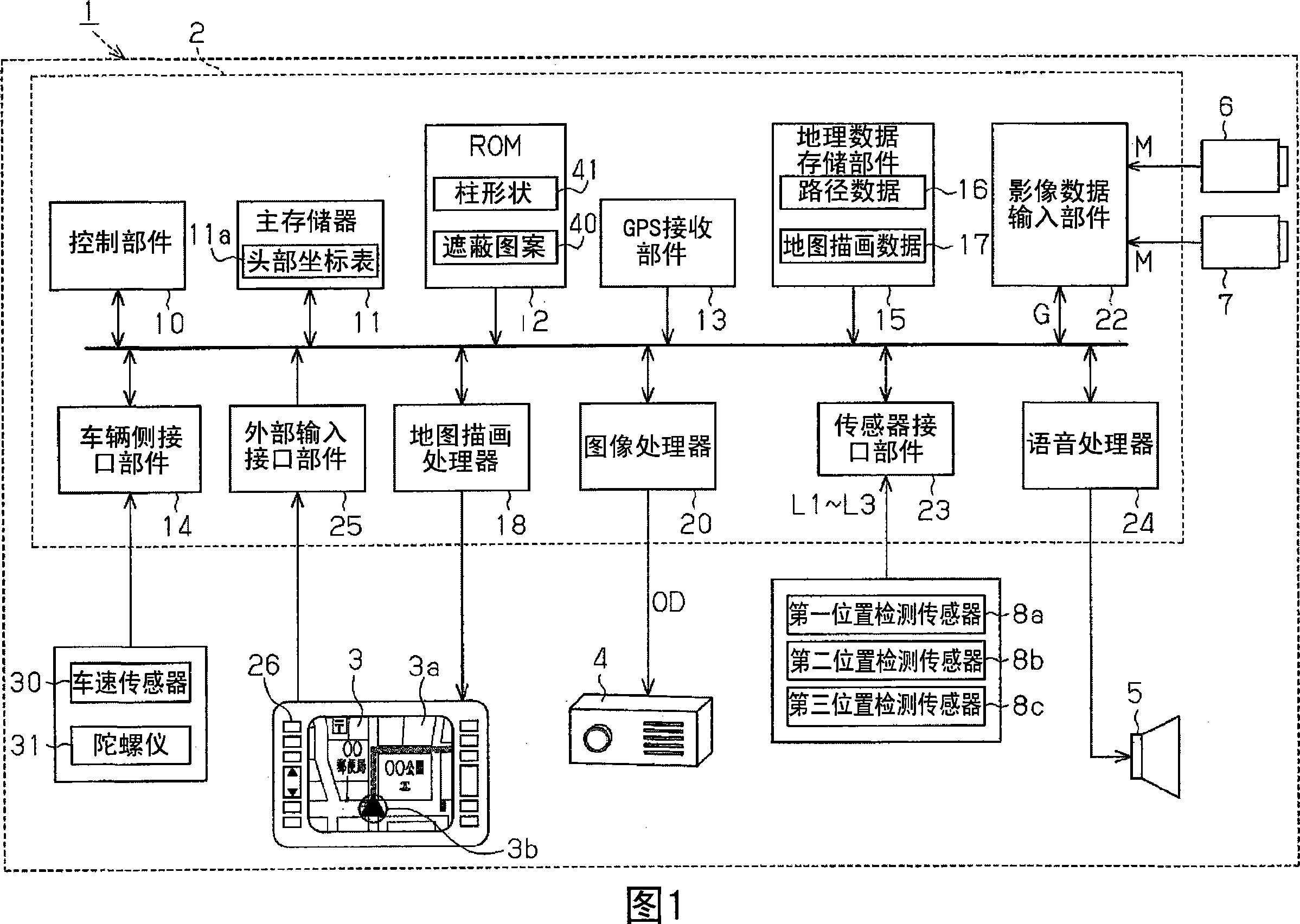
[0037] Next, an embodiment of the present invention will be described with reference to FIGS. 1 to 17 . FIG. 1 is a block diagram illustrating the configuration of a driving assistance system 1 mounted on an automobile.

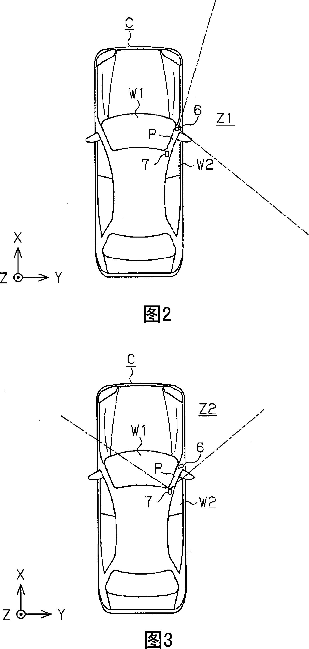
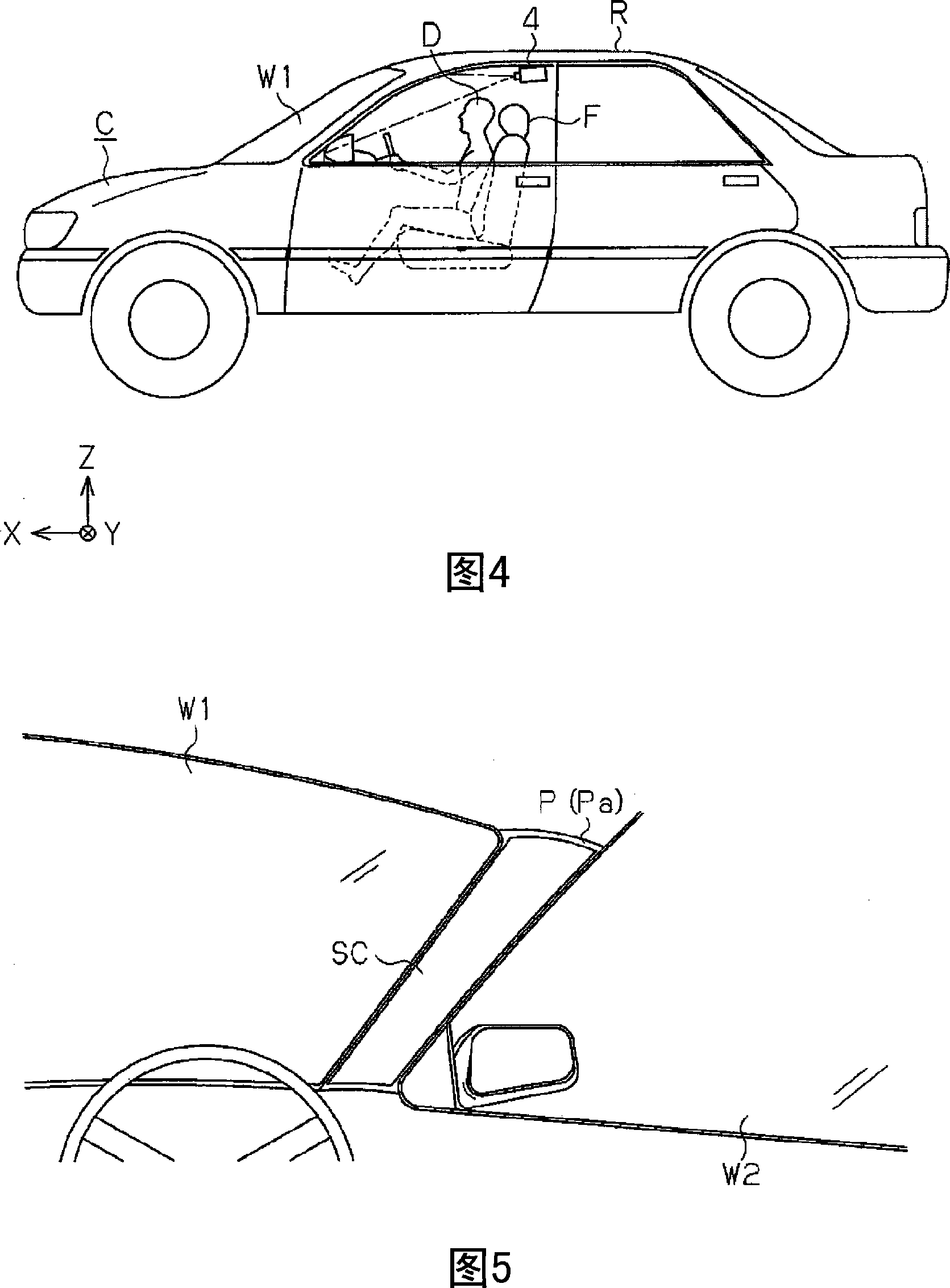
[0038] As shown in FIG. 1 , a driving assistance system 1 is installed on a vehicle C (refer to FIG. 2 ), and includes: a driving assistance unit 2 as a driving assistance device, a display 3 as a display device, a projector 4, a speaker 5, an imaging device The first camera 6, the second camera 7, and the first to third position detection sensors 8a to 8c.

[0039] The driving support unit 2 includes a control unit 10 as detection means, selection means, and angle calculation means, a nonvolatile main memory 11 , a ROM 12 , and a GPS reception unit 13 . The control unit 10 is a CPU, an MPU, or an ASIC, etc., and performs main control of each process based on a driving support program stored in the ROM 12 . The main memory 11 temporarily stores calculation ...


PUM


Abstract

A driving support unit captures an image of a driver's blind spot due to presence of a pillar of a vehicle includes at least first and second cameras which are mounted on the vehicle, a display device for displaying the image on the interior surface of the pillar and a control section for detecting position of the head of the driver, calculating a blind spot angle due to the presence of the pillar in accordance with the position of the head of the driver, and for selecting, based on the calculated angle, one of the cameras to capture the image. The first camera captures an image the major portion of which is an area to the side of the vehicle, and the second camera captures an image the major portion of which is an area to the front of the vehicle.

Description

technical field [0001] The invention relates to a driving assistance method and a driving assistance device. Background technique [0002] So far, as a device to support safe driving, an in-vehicle system has been developed in which an in-vehicle camera captures an area that becomes a driver's blind spot and displays it on a monitor or the like. As one of them, a system has been proposed in which a vehicle-mounted camera captures a blind spot area formed by a front pillar of a vehicle, and displays the captured image on the inside of the front pillar. The front pillar is the left and right pillars that support the front window and the roof. From the perspective of the driver sitting in the driving position, the front pillar is located obliquely in front and covers part of the driver's line of sight. For safety, the front pillar must It is a member that ensures the specified thickness. [0003] The above-mentioned system includes: a camera, which is installed on the vehicle...

Claims


Application Information

Patent Timeline
Patent Type & Authority Applications(China)
IPC IPC(8): H04N7/18H04N13/00G03B37/04
CPCB60R1/00B60Q9/008B60R2300/202B60R1/25
Inventor 洼田智气高木实
Owner AISIN AW CO LTD
Why Eureka
Try Eureka