

Rolling bearing device and rotary device
A technology for rolling bearings and rotating shafts, which is applied in the direction of bearing assembly, bearing components, shafts and bearings, etc. It can solve the problems of unable to stop the discharge of lubricating oil, difficult to manually stop the oil supply unit, and leakage of lubricating oil, so as to prolong the service life and reduce lubrication The effect of extended oil volume and refill interval
- Summary
- Abstract
- Description
- Claims
- Application Information
AI Technical Summary
Problems solved by technology
Method used
Image

Examples
no. 1 example
[0081] Hereinafter, a first embodiment of the present invention will be described with reference to the drawings.
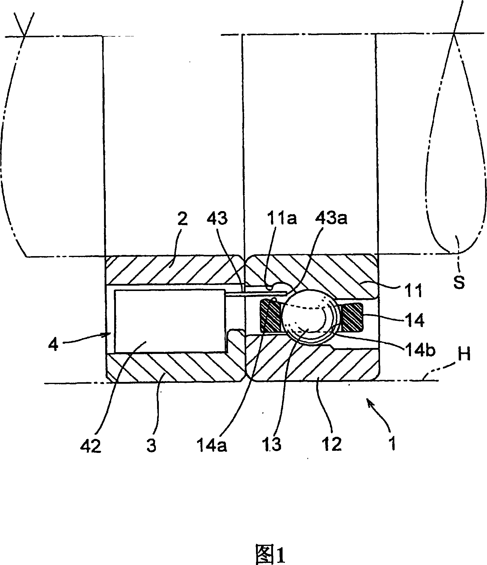
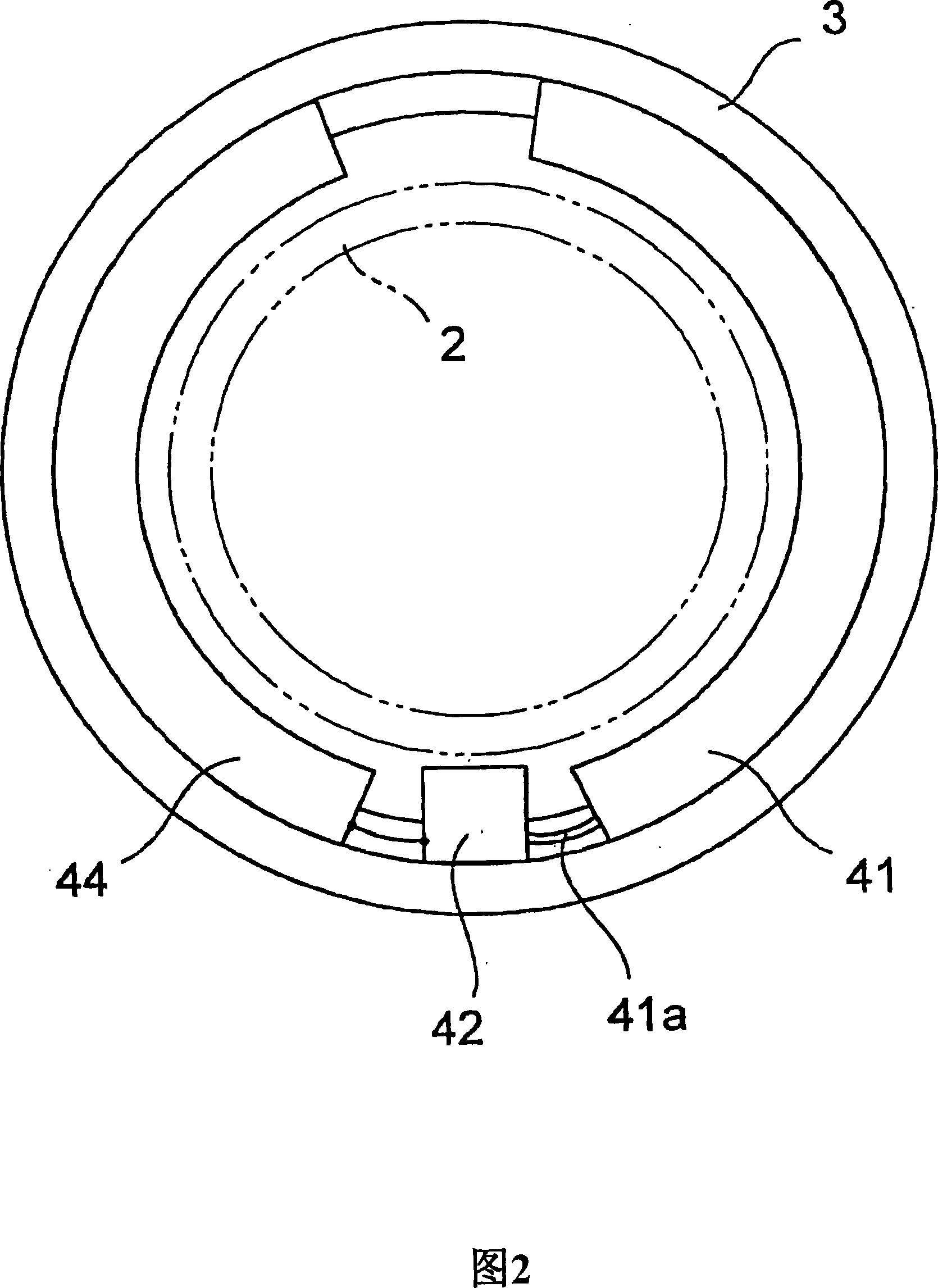
[0082] Fig. 1 is an axial sectional view of the first embodiment of the present invention, and Fig. 2 is a left side view of the outer ring spacer 3 of the first embodiment.
[0083] This embodiment shows an example of an inner ring spacer 2 and an outer ring spacer 3 arranged adjacent to each other in a radial ball bearing 1, wherein an oil supply unit 4 is arranged on the outer ring spacer 3, and the outer ring spacer The objects constitute spacers on the fixed side of the bearing 1.
[0084] The radial ball bearing 1 has a structure in which a plurality of rolling elements (balls) 13 are kept at predetermined intervals in the circumferential direction by a cage 14 between an inner ring 11 and an outer ring 12, and in this embodiment, the outer ring 12 is bonded to In the housing H as a fixed ring, and the shaft S is fixed to the inner peripheral surface of th...
no. 2 example
[0092] Although in the first embodiment that has been described above, the oil supply unit 4 is described as being disposed adjacent to the outside of the radial ball bearing 1, as shown in an axially parallel sectional view in FIG. 5 , the oil supply unit 4 may also be set in the bearing. That is, in the second embodiment shown in FIG. 5 , the radial ball bearing 70 includes an inner ring 71 , an outer ring 72 , rolling elements 3 and a cage 74 similarly to the previous embodiments. In the radial ball bearing 70 thus configured, one end side of each of the inner ring 71 and the outer ring 72 extends axially so as to increase the width dimension of each ring, and the oil supply unit 4 similar to that of the first embodiment is provided at On the extension of the outer ring 72 . Also in this embodiment, the nozzle 43 installed at the discharge port of the pump 42 is inserted between the inner peripheral surface 74a of the retainer 74 and the inner ring 71 in such a manner that...
no. 3 example
[0096] Hereinafter, a third embodiment of the present invention will be described with reference to the drawings.
[0097] 6 is a schematic diagram showing a parallel sectional view showing the configuration of a spindle as a rotary device according to a third embodiment of the present invention and a block diagram showing the configuration of an external lubricating device. In addition, FIG. 7 is an enlarged view of main parts of the configuration shown in FIG. 6, and FIG. 8 is a front view of the outer ring spacer and the oil supply unit viewed from the direction of arrow A shown in FIG. 7.
[0098] The rotary device of the third embodiment is configured such that a spindle 102 housed in a housing 101 can be rotatably supported by four radial ball bearings 103 . Each radial ball bearing 103 is a general-purpose ball bearing including an inner ring 103a fixedly mounted to the spindle 102, an outer ring 103b mounted in the housing 101, a plurality of rolling elements (balls 10...
PUM
 Abstract
Description
Claims
Application Information