Variable radio frequency signal phase-shifting circuit and its phase-shifting method

A technology of radio frequency signals and phase-shifting circuits, which is applied to circuits, electrical components, waveguide devices, etc., can solve the problems of increasing the complexity and cost of phase shifter functions, and achieves simple structure, small signal insertion loss, and pre-improvement The effect of power-fed amplifier technology

Inactive Publication Date: 2008-01-23
锐德科无线通信技术(上海)有限公司
View PDF3 Cites 29 Cited by
  • Summary
  • Abstract
  • Description
  • Claims
  • Application Information

AI Technical Summary

Problems solved by technology

At present, the phase shift range of the general-purpose variable phase shifter is about 100 degrees. If a larger range of phase shift range is to be obtained, 3 to 4 phase shifter circuits need to be cascaded, as shown in Figure 1, which increases the The complexity and cost of implementing the phase shifter function

Method used


Image

  • Variable radio frequency signal phase-shifting circuit and its phase-shifting method
  • Variable radio frequency signal phase-shifting circuit and its phase-shifting method
  • Variable radio frequency signal phase-shifting circuit and its phase-shifting method

Examples


Embodiment Construction

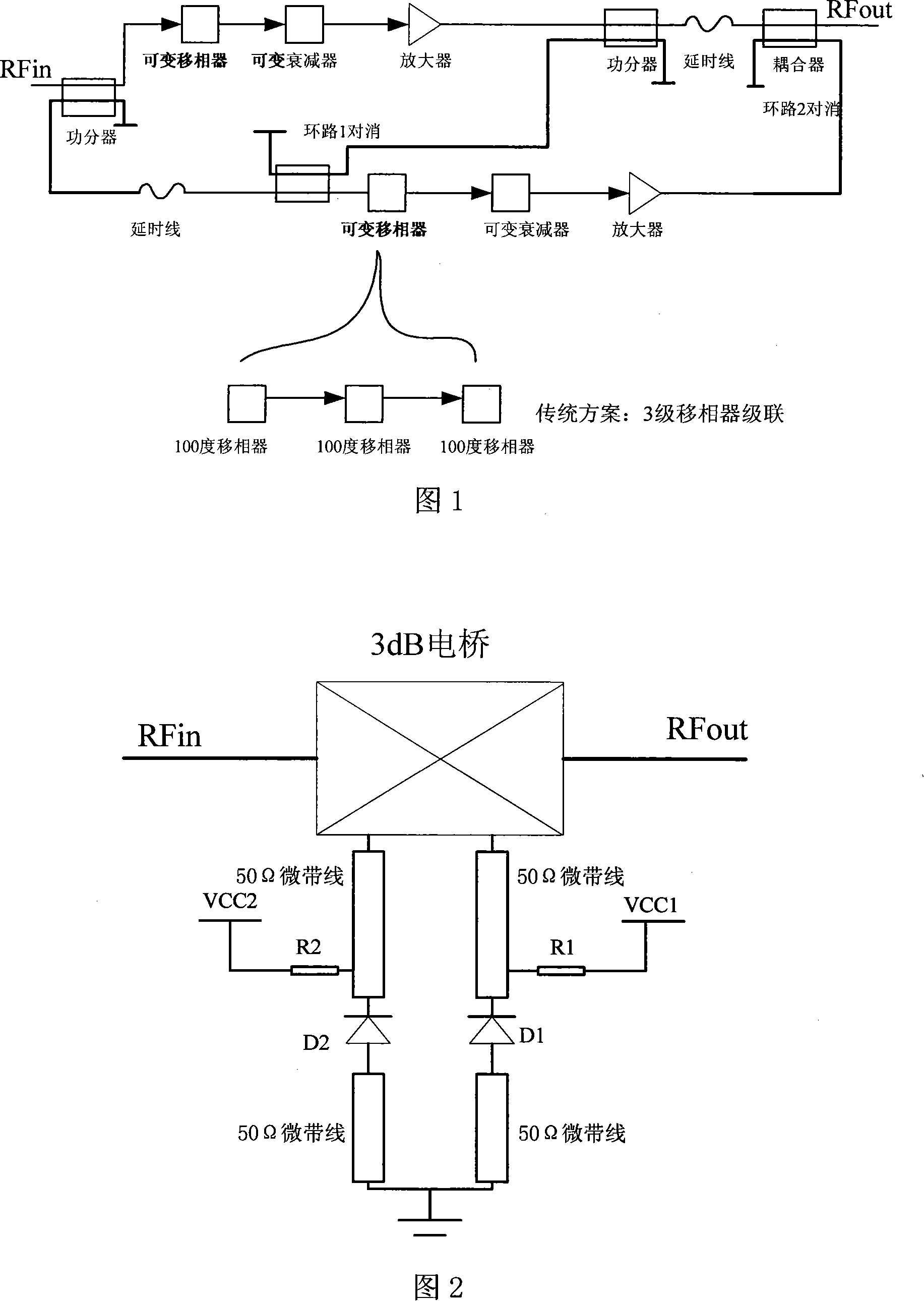
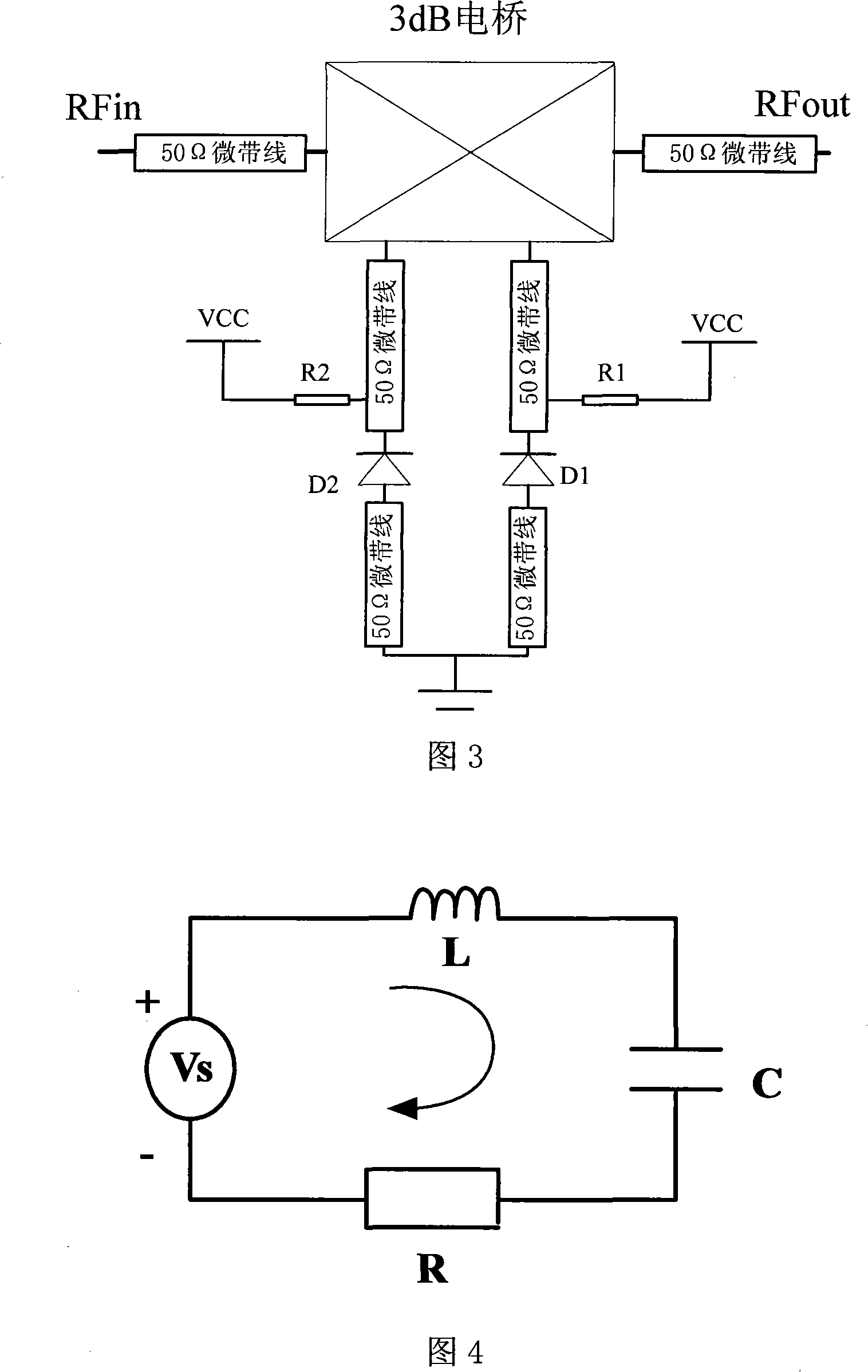
[0022] The variable radio frequency signal phase-shifting circuit of the present invention, its structure can refer to as shown in Figure 2, comprises a 3dB electric bridge, and the two phase ends of described 3dB electric bridge are connected with first resonant circuit and second resonant circuit, and described first resonant circuit A resonant circuit includes a variable capacitor D1, the variable capacitor D1 and the 3dB bridge, and the variable capacitor D1 and the ground are respectively connected through a 50Ω microstrip line at one end, and the second The resonant circuit includes a variable capacitor D2, and the variable capacitor D2 is connected to the 3dB bridge, and between the variable capacitor D2 and the ground through a 50Ω microstrip line at one end.

[0023] The variable capacitors D1 and D2 are voltage-controlled varactor devices, and the voltage control terminal VCC is connected between the voltage-controlled varactor device D1 and the 3dB bridge, and betwee...


PUM


Abstract

The present invention discloses a variable radio frequency signal phase shift circuit, which comprises a 3dB electric bridge. Wherein, the 3dB electric bridge is connected with two resonance circuits. The resonance circuit is composed of a variable capacitance. One end of the variable capacitance is connected with the 3dB electrical bridge through a 50 Omega micro-strip line. In addition, the other end of the variable capacitance is grounded through a 50 Omega micro-strip line. The present invention also discloses a radio frequency signal phase shift method. The radio frequency signal enters into the 3dB electric bridge and then is divided into two totally symmetric paths, which respectively enter into two resonance circuits to adjust the variable capacitance and the 50 Omega micro-strip line of two resonance circuits, accordingly changing two paths of signals transmitting through a first and a second resonance circuit. And then, two paths of signals are reflected to the 3dB electric bridge for secondary synthesis and are output from one isolation terminal of the 3dB electric bridge. The present invention has the advantages of simple structure, easy execution, lower cost, large adjusting range, lower insertion loss and control over phase shift range of a phase shifter and stepping voltage.

Description

technical field [0001] The invention relates to a signal phase shifting circuit, in particular to a variable radio frequency signal phase shifting circuit. The invention also relates to a radio frequency signal phase shifting method. Background technique [0002] RF power amplifiers are widely used in the field of wireless communication. In recent years, with the increase of signal modulation methods, the efficiency and linearity requirements of power amplifiers are increasing, so feedforward technology is widely used in power amplifier design, and signal phase shifting is one of the core conditions for realizing this technology . [0003] In the past RF circuit phase shifter design, although the circuit shape is various, the principle is usually to use the signal to pass through the capacitor to generate phase shift, and only derive different circuits according to the application of the phase shifter in different environments. Design form and features. [0004] For exam...

Claims


Application Information

Patent Timeline
Patent Type & Authority Applications(China)
IPC IPC(8): H01P1/18
Inventor 夏瑜夏天
Owner 锐德科无线通信技术(上海)有限公司
Why Eureka
Try Eureka