
Draw ring type tripper used for optoelectronic module

A technology of unlocking device and optoelectronic module, applied in the direction of electrical components, coupling of optical waveguides, electromagnetic wave transmission systems, etc., can solve the problems of unlocking function failure, reset, loss of locking function, etc. The effect of reliability

Inactive Publication Date: 2010-05-19
宝得粉末注射成形(常熟)有限公司
View PDF6 Cites 0 Cited by
  • Summary
  • Abstract
  • Description
  • Claims
  • Application Information

AI Technical Summary

Problems solved by technology

Among them, the push-pull structure uses a push block to lift up the locking shrapnel of the metal shielding cage to unlock the module. The problem with this structure is that due to the increasingly high EMI requirements of modern communication equipment, the metal shielding cage and equipment The panels must fit very tightly, that is to say, the movable gap of the lock shrapnel of the metal shielding cage is extremely small. Therefore, the above-mentioned structure of pushing the metal shielding cage lock shrapnel by the push block cannot be used on new equipment.
This ring-pull unlocking device can be widely used in modern communication equipment with closely arranged metal shielding cages, but the following problems have been exposed in the actual use process: First, due to the small structure and complex shape of this product, the brake pads The return spring adopts a pressure spring with an outer diameter of only 0.9mm and a length of 8mm. Its elasticity is poor and it is easy to bend off. After the brake pad is pushed forward under the action of the pull ring, it cannot be reset, resulting in the bump being unlocked. Afterwards, it cannot be raised and reset and loses the locking function; secondly, because the bump and the brake pad are made separately, the up and down movement of the bump is controlled by the brake pad, and sometimes the head of the brake pad and the position of the bump The sliders are stuck to each other and the unlocking function fails; moreover, the spring acting on the bump is also a compression spring with an outer diameter of only 0.9mm, which also makes the bump unable to reset or insufficient reset, resulting in failure to lock or The lock is not secure; in addition, the pull ring is movably connected to the outside of the module shell through a pair of pins. Because the pins are not easy to process, it is not easy to install on the pull ring, which increases the difficulty of processing the parts; and, there are many parts and installation , The unloading is cumbersome, which will affect the reliability of the action

Method used


Image

  • Draw ring type tripper used for optoelectronic module
  • Draw ring type tripper used for optoelectronic module

Examples


Embodiment Construction

[0016] In order to enable examiners, especially the public, to further understand the structural features and beneficial effects of the present invention, the specific implementation of the present invention is described in detail as follows in conjunction with the accompanying drawings:

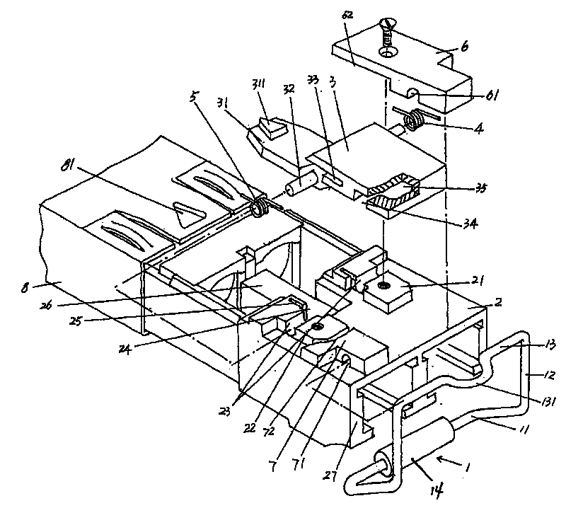
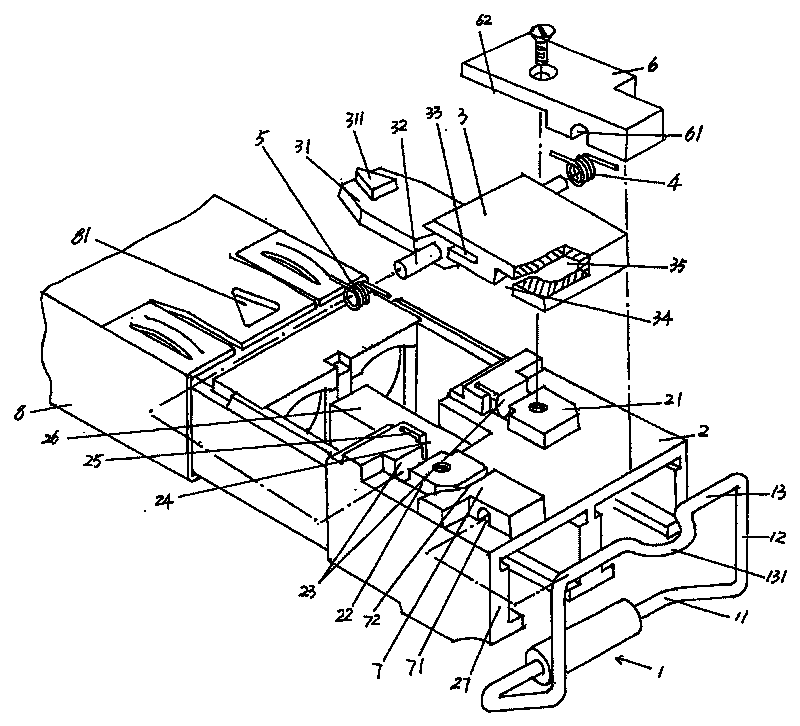
[0017] Please refer to the accompanying drawings, the module housing 2 of the present invention is a rectangular cavity, on which a pair of first and second bosses 22, 21, a pair of brake disc shaft grooves 23, a pair of torsion springs are respectively formed. Cavity 24 and a pair of first torsion spring foot slots 25 and lock seat cavity 26, the light port end face 27 on one side is used to put a pair of side arms 12 of pull ring 1, the section of a pair of brake pad shaft slots 23 The shape is U-shaped. The pull ring 1 of the present invention is composed of a pull ring body 11, a pair of side arms 12 extending on the pull ring body 11, a rotating shaft 13 extending between the tops of th...


PUM


Abstract

A pull-tab type unlocking device for photoelectric modules belonging to the technical field of optical communications comprises a pull-tab, a left pressing block and a right pressing block fixed on amodule shell, a first rotating shaft groove and a second rotating shaft groove formed on the pressing block, a locking holder formed at a front end of a braking plate, a lock catch on the locking holder, a pair of braking plate rotating shafts extended from two central sides, a third rotating shaft groove and a cam cavity formed below a back end, a left torsional spring and a right torsional spring mounted on these two braking plate rotating shafts. Wherein, these two braking plate rotating shafts are rotationally pivoted into a pair of braking plate rotating shaft grooves. The pull-tab is composed of a pull-tab, a pair of lateral arms, rotating shafts and cam wheels. The rotating shaft is pivoted into the first, the second and the third rotating shaft groove. The cam wheel matches the cam cavity. The present invention has the advantages of compact structure, fewer parts, easy mounting and detachment, high action reliability, more simple unlocking and easy parts processing and production. The pull-tab is provided with a self-return function and suitable for more compact caging equipments.

Description

technical field [0001] The invention relates to an unlocking device for a hot-swappable photoelectric module in the field of optical communication, in particular to a ring-pull unlocking device for a photoelectric module. Background technique [0002] At present, the unlocking device of the hot-swappable photoelectric module mainly has two structures of a push-pull type or a ring-pull type. Among them, the push-pull structure uses a push block to lift up the locking shrapnel of the metal shielding cage to unlock the module. The problem with this structure is that due to the increasingly high EMI requirements of modern communication equipment, the metal shielding cage and equipment The panels must fit very tightly, that is to say, the movable gap of the lock spring of the metal shielding cage is extremely small. Therefore, the above-mentioned structure of pushing the lock spring of the metal shield cage by the push block cannot be used on new equipment. The ring-pull structu...

Claims


Application Information

Patent Timeline
Patent Type & Authority Patents(China)
IPC IPC(8): H04B10/02H04B10/12G02B6/42
Inventor 顾祖良
Owner 宝得粉末注射成形(常熟)有限公司
Learn More