Apparatus and method for supporting automatic optical fiber connecting configuration of optical transmission equipment

A technology of optical fiber connection and optical transmission, applied in the field of optical communication, can solve problems such as inability to support remote operation, achieve the effect of improving maintenance efficiency and saving daily maintenance costs

Inactive Publication Date: 2008-01-23
STATE GRID CORP OF CHINA +1
0 Cites 17 Cited by

AI-Extracted Technical Summary

Problems solved by technology

[0003] Based on the implementation characteristics of the above-mentioned optical transmission equipment using direct optical fiber connection, when performing maintenance operations such as system cutover, upgrade and expansion during the equipment commissioning period, it is necessary to use manual on-site dir...

Abstract

The present invention discloses a device and a method to support automatic fiber access configuration of optical transmission equipments, which comprise an equipment control system to realize remote control over all processing units of the equipment, including remote cross configuration to cross matrix units of equipment nodes, a management control communication channel to provide a physical transmission channel for a network management system with all equipment processing units under its management, all function processing units of node equipments to realize optical signal transmission in form of an internal fiber access through an optical interface, a cross matrix processing unit to realize I/O optical interface connection amongst all function processing units of node equipments and conduct cross configuration to connected optical signals. The method and the device adopts optical/electrical cross matrix to realize automatic link and automatic equipment type conversion amongst fiber equipments, achieve intelligent and automatic configuration, save cost on daily equipment maintenance and increase maintenance efficiency.

Application Domain

Electromagnetic network arrangementsFibre transmission +1

Technology Topic

Image

  • Apparatus and method for supporting automatic optical fiber connecting configuration of optical transmission equipment
  • Apparatus and method for supporting automatic optical fiber connecting configuration of optical transmission equipment
  • Apparatus and method for supporting automatic optical fiber connecting configuration of optical transmission equipment

Examples

  • Experimental program(1)

Example Embodiment

[0030] The further implementation of the present invention will be described in detail below in conjunction with the accompanying drawings.
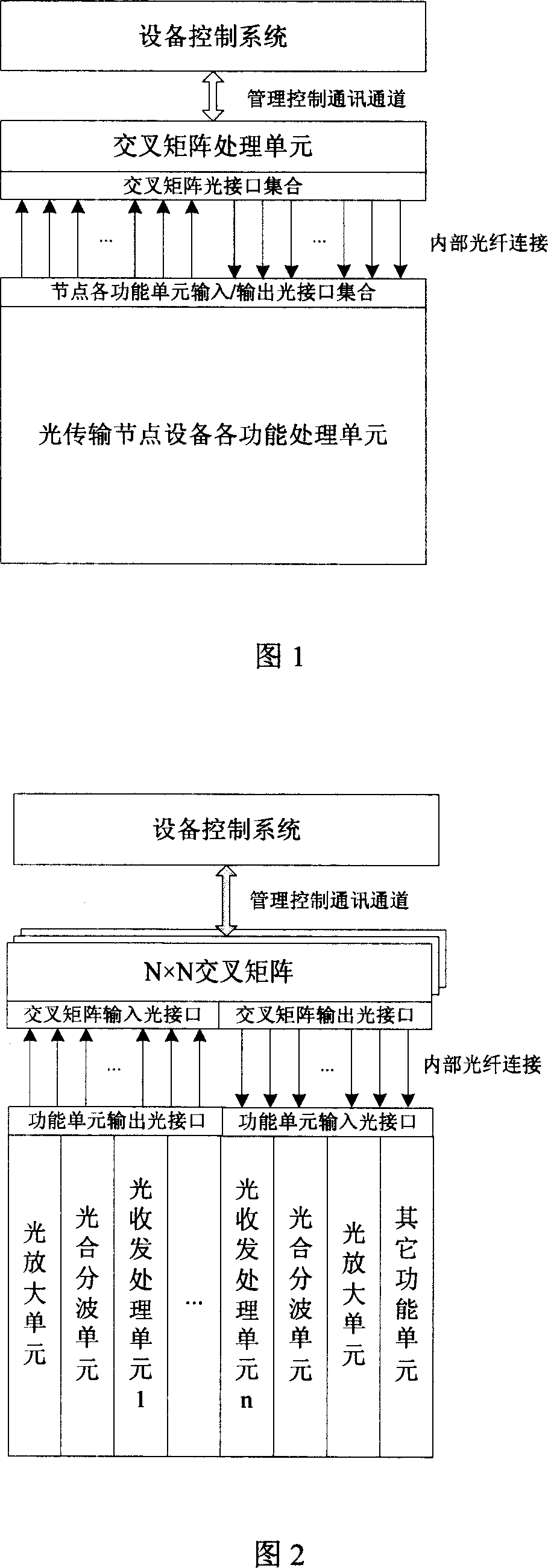
[0031] The present invention provides a device and method for supporting automatic optical fiber connection configuration of optical transmission equipment. The device structure includes the following functional parts, as shown in Figure 1:
[0032] (1) Equipment control system. The main function of the equipment control system is to provide equipment managers with operation terminals for equipment management and control. The equipment control system can realize the control of equipment through the network and internal management control communication channels of the equipment according to the operation instructions of the equipment managers. The remote control operation of each processing unit includes the remote cross configuration of the cross matrix unit of the equipment node.
[0033] (2) The management and control communication channel, the main function of the management and control communication channel is to provide a physical transmission channel for the message communication between the network management system and the processing units of the equipment it manages.
[0034] (3) The functional processing units of the node equipment mainly include the functional parts of the optical transmission equipment, such as the optical amplification unit, the optical multiplexing and demultiplexing unit, the optical transceiver processing unit, and the optical monitoring unit. The optical signal transmission is carried out between the relevant functional processing units through the optical interface and the internal optical fiber connection.
[0035] (4) Cross-matrix processing unit. As the core component of the present invention, the cross-matrix processing unit is mainly used to realize the input/output optical interface connection between the functional processing units of the node device, and realizes the connection of the connected optical signal by receiving external control instructions. Cross-configuration operation. It can be composed of one or more optical/electric cross matrix modules to realize the cross control capability of N groups of incoming/outgoing optical signals. The value of N should not be less than the sum of the number of optical interfaces of each functional unit of the system equipment.
[0036] The present invention realizes the automatic optical fiber connection configuration function of the device by adding a cross matrix processing unit on the basis of the traditional optical transmission device, and the method steps for its realization mainly include:
[0037] (1) In the initial assembly stage of the equipment, the optical interfaces of the functional processing units in the node are fixedly connected with the optical interfaces of the cross matrix processing unit in an internal optical fiber connection mode. According to the principle of consistent optical signal flow, the input/output optical interfaces of the internal processing unit are respectively connected with the output/input optical interfaces of the cross-processing unit. And store the optical fiber connection relationship information inside the node in the equipment control system database.
[0038] (2) Through the equipment control system, the operator determines the optical interface connection configuration that needs to be adjusted during the opening and maintenance stage according to the connection information of the internal optical interface of the initial node, according to the actual configuration needs of the system, and sends it to the equipment control system in the form of message instructions. The cross matrix processing unit sent to the node.
[0039] (3) The cross matrix processing unit of the node receives the cross configuration instruction from the device control unit, and interprets the source port and sink port of the fiber connection that need to be configured from the instruction information, and then performs the cross action to complete the source port and sink port. The optical fiber connection between the nodes realizes the remote automatic configuration operation of the optical signal connection inside the node. The newly confirmed cross configuration result information will update the database of the device control system to support subsequent possible optical interface configuration adjustment operations.
[0040] The following Fig. 2 is an application example of the device and method based on the present invention, combined with WDM optical transmission equipment.
[0041] As shown in Figure 2, each functional processing unit of the traditional WDM node equipment includes an optical amplifying unit, an optical multiplexing and demultiplexing unit, an optical transceiver processing unit, an optical monitoring unit, etc. On this basis, the present invention adds N×N cross matrix components. The cross matrix can provide a cross configuration for N groups of input/output optical interfaces, and the internal implementation can use different technologies such as optical cross or electrical cross.
[0042] For a WDM system node configuration with a bidirectional 40-wave capacity, the value of N can generally be 256. Considering the integration degree of the cross device used, the 256×256 cross matrix can be integrated with multiple sub-cross matrixes, such as functions Decompose into four 64×64 cross matrices to achieve.
[0043] (1) OLA node is upgraded to OADM node
[0044] The internal optical fiber connection of the OLA node (optical line amplifying node, that is, only realizing the amplification of the optical signal of the line, without the business up and down configuration) is shown in Figure 3. The optical amplifiers in the two line directions of the OLA node (OPA: optical preamplifier; OBA: optical post amplifier) ​​OPA1/OBA1 and OPA2/OBA2 have the same internal optical interfaces as the SMU (optical cross matrix unit) of the node. Two sets of input/output optical interfaces (I1/O1 and I2/O2) are connected by the internal optical fiber of the node.
[0045] The cross matrix inside the node and the optical interface connection information of the functional unit need to be stored in the network management system. The contents of the stored table are shown in Table 1:
[0046] Table 1 OLA site cross matrix and functional unit optical interface connection information table
[0047] Handling unit name
[0048] Forward output signal outside the node
[0049] According to the logical relationship of the optical signal of the system, the cross relationship of the optical interface occupied by the cross matrix is ​​configured through the network management system. The configuration data information is shown in Table 2 below:
[0050] Table 2 OLA site cross matrix cross configuration information table
[0051] Connection source
[0052] When the configuration command of the equipment control system is sent to the cross matrix unit of the node through the management and control communication channel, the cross matrix unit will switch after receiving the command to realize the connection of the internal optical fiber interface of the node to meet the optical signal connection requirements of the system, and the internal cross matrix Connect, as shown by the dashed line in Figure 3.
[0053] When the OLA node needs to be upgraded to an OADM node (optical add/drop station, with optical amplification function, but also with optical wavelength signal add/drop function), it is necessary to add two line-direction photosynthesis/demultiplex units ( OMU1/ODU1 and OMU 2/ODU2), corresponding to the optical transceiver processing unit of wavelength 1 to wavelength N, for example, N=2 (LOTU1, LOTU2,; ROTU1, ROTU2). First, it is necessary to connect the optical interfaces of the processing units that need to be added in the node system to the spare optical interfaces of the node cross matrix, and the internal optical fiber connection of the node is shown in Figure 4.
[0054] The cross matrix inside the node and the optical interface connection information of the functional unit need to be stored in the network management system. The contents of the stored table are shown in Table 3:
[0055] Table 3 OADM site cross matrix and functional unit optical interface connection information table
[0056] Handling unit name
[0057] Input port 2
[0058] According to the logical relationship of the optical signal of the system, the cross relationship of the occupied optical interfaces of the cross matrix is ​​configured through the network management system. The configuration data information is shown in Table 4 below, and the cross relationship after configuration is shown by the dotted line in Figure 4:
[0059] Table 4 OADM site cross matrix cross configuration information table
[0060] Connection source
[0061] Light entrance 86 (I86)
[0062] When the configuration command of the network management system is sent to the cross matrix unit of the node through the management control communication channel, the cross matrix unit performs the switching action after receiving the command to realize the internal optical fiber interface connection of the node to meet the optical signal connection requirements of the system.
[0063] (2) Add optical line power adjustable attenuator at the node
[0064] The following is an example of another common maintenance operation of optical transmission equipment. On the basis of the OADM node shown in Figure 4 above, two line directions of optical line power adjustable attenuator (LAC1 and LAC2) processing units are added.
[0065] The cross matrix inside the node and the optical interface connection information of the functional unit need to be stored in the network management system. The contents of the stored table are shown in Table 5:
[0066] Table 5 OADM site cross matrix and functional unit optical interface connection information after adding LAC
[0067] Handling unit name
[0068] number
[0069] Output port 1
[0070] According to the logical relationship of the optical signals of the system, the network management system configures the cross relationship of the optical interfaces occupied by the cross matrix. The configuration data information is shown in Table 6 below, and the relationship after configuration is shown by the dotted line in Figure 5:
[0071] Table 6 Cross configuration information table of OADM site cross matrix after adding LAC
[0072] Connection source
[0073] ...
[0074] When the configuration command of the network management system is sent to the cross matrix unit of the node through the management control communication channel, the cross matrix unit performs the switching action after receiving the command to realize the internal optical fiber interface connection of the node to meet the optical signal connection requirements of the system.
[0075] Figure 2 depicts an example of the application of the present invention in an optical communication dense wavelength division transmission system. Figure 3 describes the process of automatically completing the configuration of optical fiber connections through the equipment control system under this architecture.
[0076] Step 1: Connect the optical transmission unit, optical pre-amplifier unit OPA, and optical post-amplifier unit OBA used in the OLA site to the input and output ports of all optical fibers in accordance with the ports in the figure and the optical cross matrix. The optical fiber connection information is recorded in the equipment control system as shown in Table 1;
[0077] Step 2: Configure the cross relationship of the cross matrix through the equipment control system according to the needs of the actual application (in this case, the OLA site). After the optical signal arriving at the site is amplified by the pre-amplifier unit OPA, it should enter the post-amplifier unit OBA. In the device control system of the present invention, a setting command is issued to configure the connection of ports I1 to O1 to realize the connection of external input signals to the input port of the preamplifier unit OPA; to configure the connection of ports I2 to O2 to realize the output of the preamplifier unit OPA The port is connected to the input port of the post-amplifier unit OBA; the connection of the configuration port I3 to O3 realizes the output of the post-amplifier unit OBA as the output of the cross matrix.
[0078] Step 3: After the cross matrix receives the instruction from the control system, it will cross-connect according to the configured cross relationship;
[0079] Step 4: Transition from OLA site to OADM site. Increase the equipment units required by the OADM site, including the optical forwarding unit, the optical multiplexing unit OMU, and the optical demultiplexing unit ODU. Connect the fiber input and output ports of the newly added equipment unit to the optical crossover matrix in turn, as shown in Figure 4.
[0080] Step 5: Modify the cross relationship of the optical cross matrix on the equipment control system. In the device control system of the present invention, the setting command is issued to configure the connection of ports I47 to O47 and the connection of I48 to O48 to realize the connection of the service signal of the optical forwarding unit and the OMU channel port of the optical multiplexing unit; the connection of the configuration port I87 to O2 realizes the connection The connection of the post-wave signal to the optical post-amplification unit OBA. The receiving direction can be deduced by analogy. Configure the connection of port I2 to O7 to realize the connection of the output signal of the preamplifier to the ODU multiplexing port of the optical demultiplexer board; configure the connection of I8 to O8, and I9 to O9 to realize the service drop. The final cross relationship is shown in Table 4.
[0081] Step 6: After the cross matrix receives the instruction from the control system, it will cross-connect according to the configured cross relationship.
[0082] This completes the automatic configuration of the optical fiber connection between the devices and the automatic conversion of the site type from the OLA site to the OADM site.

PUM

no PUM

Description & Claims & Application Information

We can also present the details of the Description, Claims and Application information to help users get a comprehensive understanding of the technical details of the patent, such as background art, summary of invention, brief description of drawings, description of embodiments, and other original content. On the other hand, users can also determine the specific scope of protection of the technology through the list of claims; as well as understand the changes in the life cycle of the technology with the presentation of the patent timeline. Login to view more.

Similar technology patents

Classification and recommendation of technical efficacy words

Why Eureka
Try Eureka