Fuel feeding device

A fuel supply device, fuel technology, applied in the direction of liquid fuel feeder, charging system, engine components, etc.

Inactive Publication Date: 2008-01-23
AISAN IND CO LTD
View PDF1 Cites 11 Cited by
  • Summary
  • Abstract
  • Description
  • Claims
  • Application Information

AI Technical Summary

Problems solved by technology

Since such control modules are usually provided with heat generating electronics such as

Method used


Image

  • Fuel feeding device
  • Fuel feeding device
  • Fuel feeding device

Examples


no. 1 example

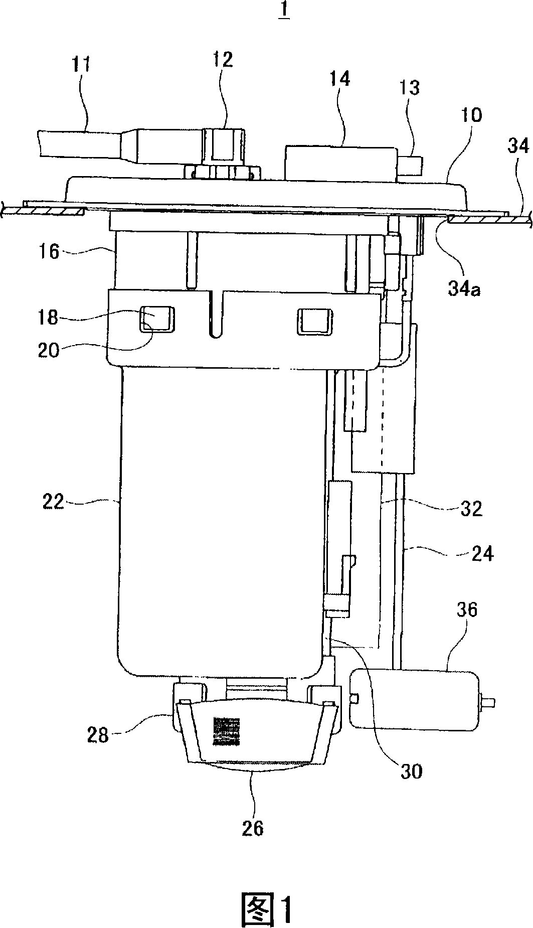
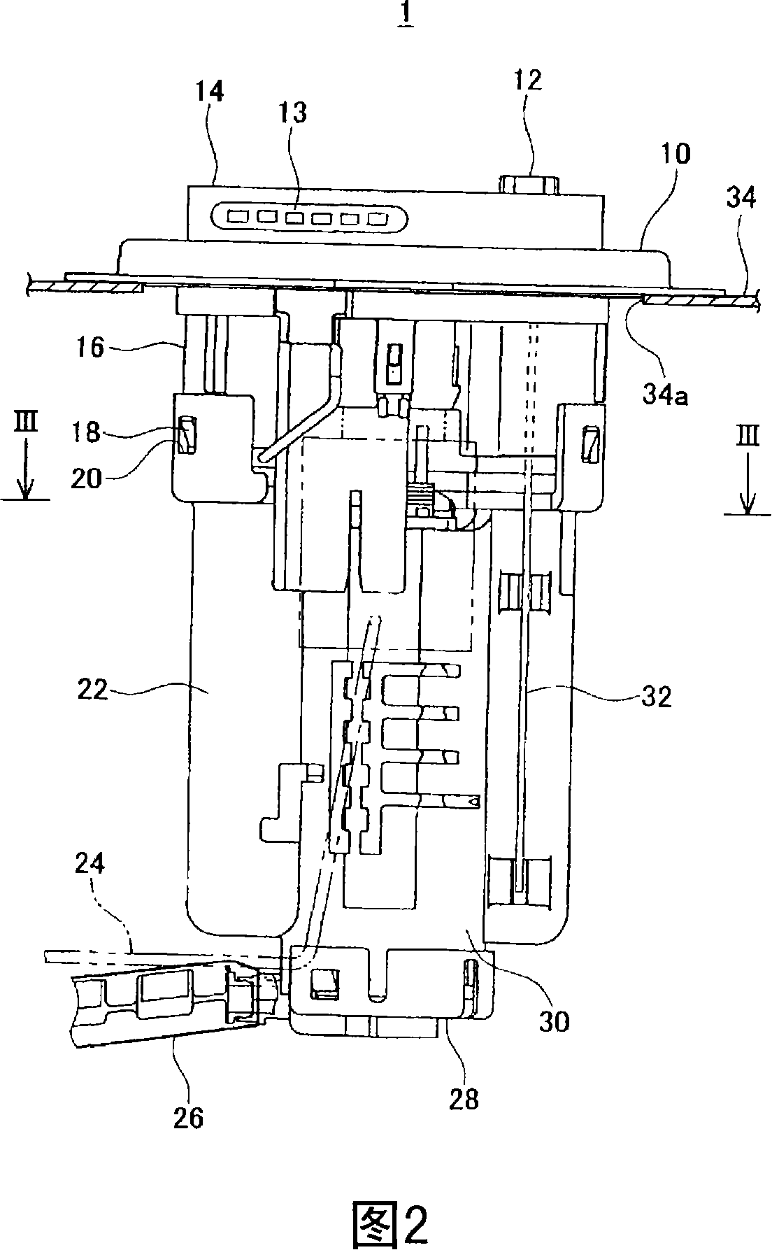
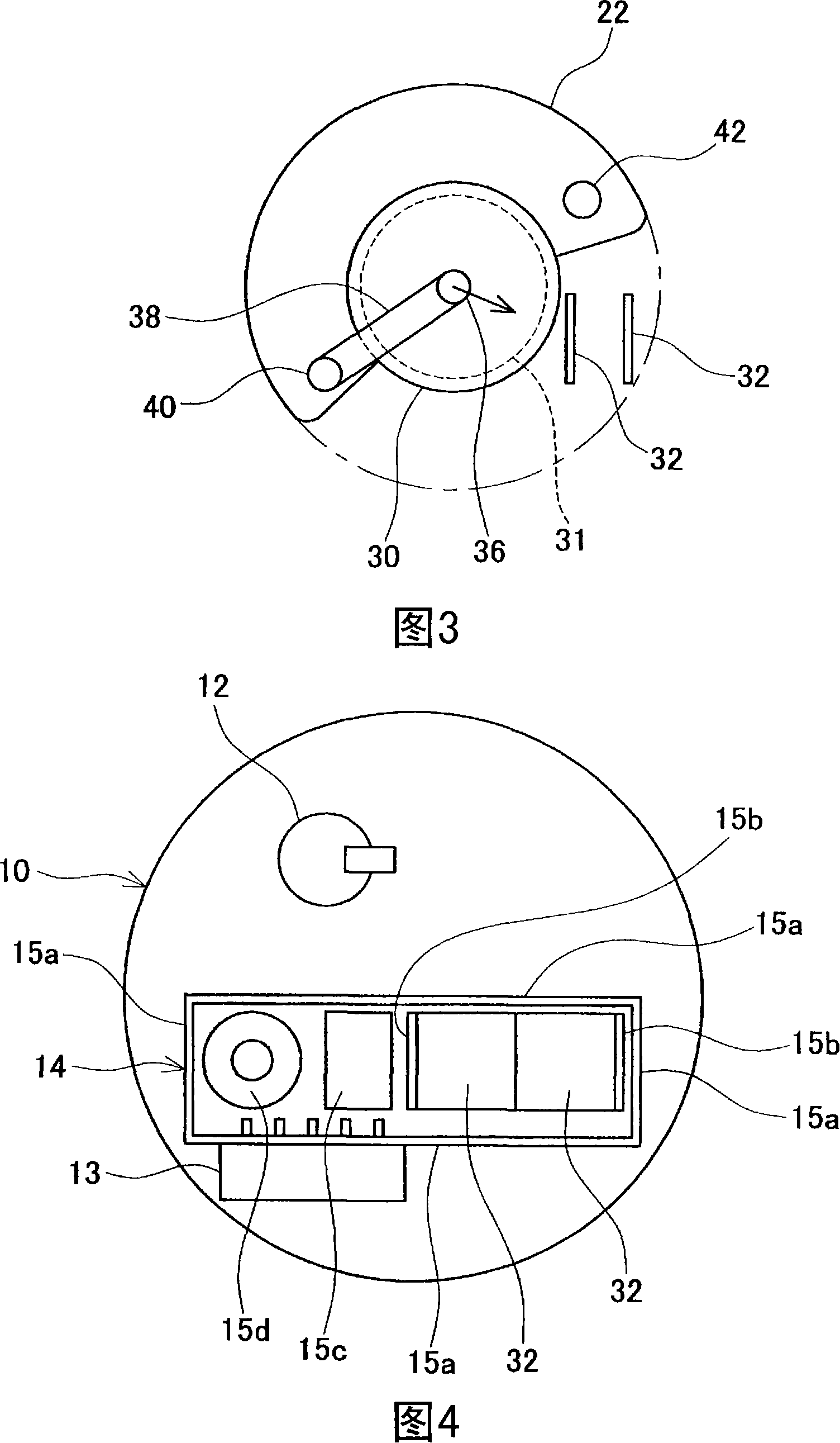
[0083] A fuel supply device of a first embodiment of the present invention will be described below. First, the entire structure of the fuel supply device will be described with reference to FIGS. 1 to 3 . As shown in FIGS. 1 and 2 , the fuel supply device 1 includes a pressure plate 10 molded from an insulating resin material. The pressure plate 10 is connected with a mounting hole 34 a formed in the upper surface of the fuel tank 34 . The mounting hole 34 a is covered by the pressing plate 10 when the pressing plate 10 is attached to the mounting hole 34 a. The circuit case 14 and the discharge pipe connection portion 12 are formed on the upper surface of the platen 10 (the outer surface of the fuel tank 34 ).

[0084] The circuit case 14 accommodates a control module (described in detail later). The connector 13 is integrally formed with the circuit case 14 . The control module housed in the circuit case 14 is connected to the connector 13 . A power source such as a bat...

no. 2 example

[0121] A fuel supply device according to a second embodiment of the present invention will be described below with reference to FIGS. 21 to 23 . As shown in FIG. 21 , the fuel supply device of the second embodiment includes a pressure plate 110 attached to a mounting hole of a fuel tank 100 . The pressure plate 110 is molded from an insulating resin material. A fuel discharge passage 108 is formed in the pressure plate 110 . A branch passage 108 a is formed in the middle of the fuel discharge passage 108 . A pressure regulator (safety valve) 112 is connected to the end of the branch passage 108a. A discharge pipe connection portion 111 is formed at an end of the fuel discharge passage 108 . A discharge pipe (not shown) is connected to the discharge pipe connection portion 111 . An injector (not shown) is connected to the other end of the discharge pipe, and fuel is supplied from the injector into the engine.

[0122] The control circuit section 114 is connected to the pla...


PUM


Abstract

A fuel feeding device capable of suppressing the excessive heating of a fuel supplied from a fuel pump into an internal combustion engine even if a control module is cooled. The fuel feeding device (1) comprises a set plate (10) installed in the mounting hole (34a) of a fuel tank (34), the electric fuel pump (30) installed on the inner surface of the set plate (10), the control module (14) installed on the outer surface of the set plate (10) and driving the fuel pump (30) by an electric power supplied from the outside, and a heat radiating member (32) radiating a heat generated in the control module (14). One end of the heat radiating member (32) is thermally connected to the control module (14), and the other end of the heat radiating member (32) is projected from the inner surface of the set plate (10) downward.

Description

technical field [0001] The present invention relates to a fuel supply device for supplying fuel to an internal combustion engine, such as an engine of a motor vehicle. In particular, the present invention relates to a cooling structure of a control module for controlling a fuel supply device. Background technique [0002] In recent years, a fuel supply device provided with a control module that controls a fuel pump has become mainstream. Since such control modules are usually provided with heat generating electronic devices, such as power transistors or similar, cooling the control modules has become a significant problem. A cooling structure for cooling a control module is described in Japanese Patent Laid-Open No. 2001-99029. [0003] The fuel supply device includes a set plate covering a mounting hole of the fuel tank. A bracket is formed on the lower surface of the pressure plate (inner surface of the fuel tank). The fuel pump is connected to the bracket. The circui...

Claims


Application Information

Patent Timeline
IPC IPC(8): F02M37/20F02M37/10
Inventor 山本修司井上铁治
Owner AISAN IND CO LTD
Why Eureka
Try Eureka