Device for pulling out a yarn end

A technology of pulling out device and yarn end, applied in the direction of piecing device, spinning machine, transportation and packaging, etc., can solve the problems of bad packages containing yarn debris and so on

Active Publication Date: 2008-01-30
MURATA MASCH LTD
View PDF1 Cites 14 Cited by
  • Summary
  • Abstract
  • Description
  • Claims
  • Application Information

AI Technical Summary

Problems solved by technology

In this case, winding is restarted with the end Yt side of the yarn end Y' becoming the cut end Ys and

Method used


Image

  • Device for pulling out a yarn end
  • Device for pulling out a yarn end
  • Device for pulling out a yarn end

Examples


Embodiment Construction

[0019] Hereinafter, a preferred embodiment of the present invention will be described with reference to the drawings.

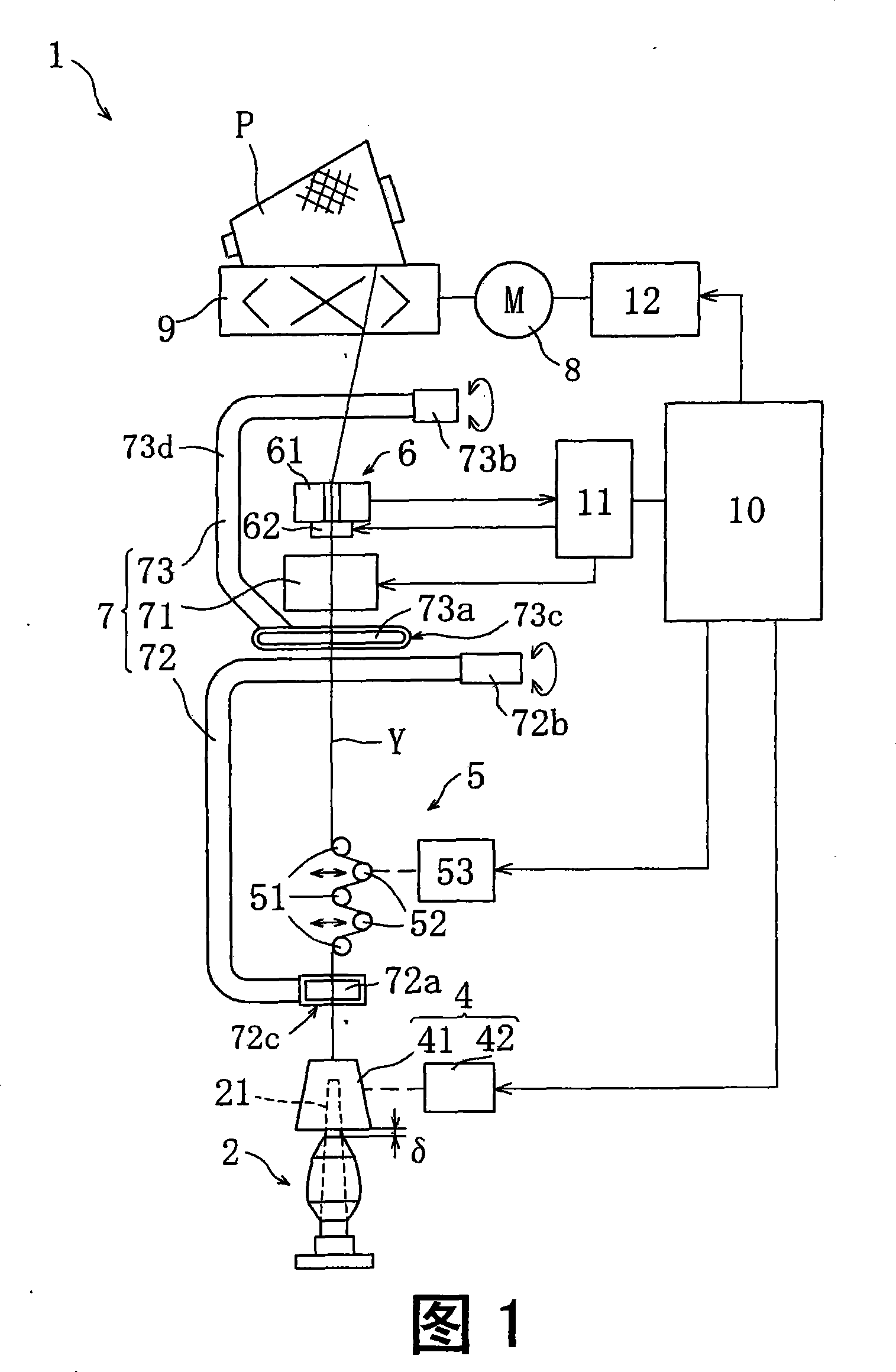
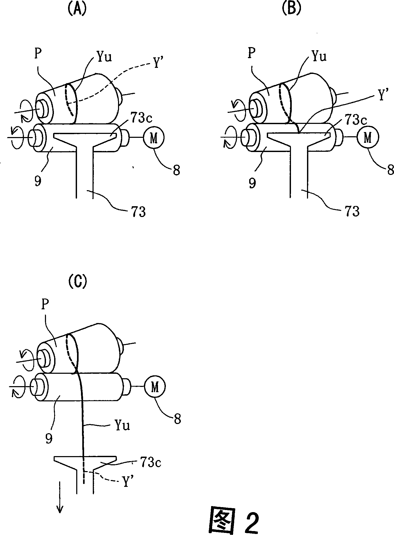
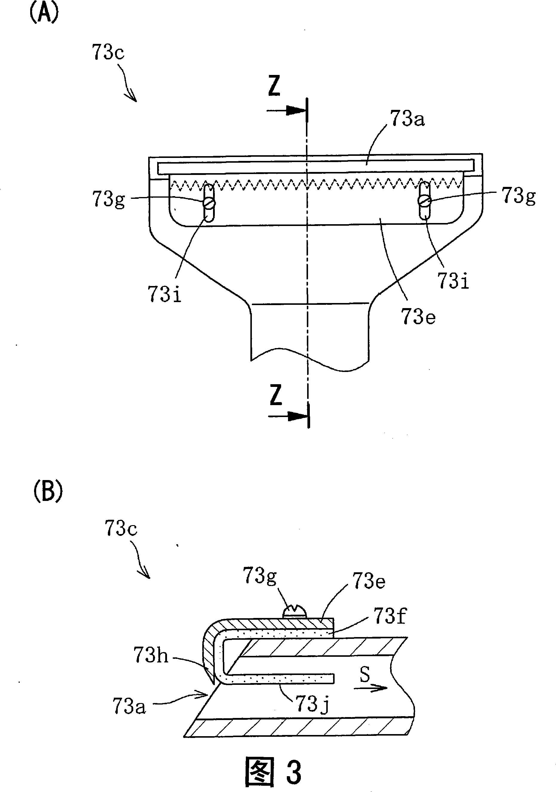
[0020] 1 is a front view showing a winding unit to which a yarn end pulling device according to an embodiment of the present invention is applied. FIG. (A) plan view and (B) side sectional view along line Z-Z showing the suction part of the yarn end pulling device according to the embodiment of the present invention, and FIG. 4 shows the yarn end pulling out of the yarn end pulling device in FIG. state diagram.

[0021] First, an automatic winder to which the yarn end pulling device according to this embodiment is applied will be roughly described. An automatic winder is a device that unwinds a yarn supply bobbin produced by a spinning machine etc. to form a winding package. The winding unit 1 constituting this automatic winder is, as shown in FIG. Arranged in the upper part and constituted.

[0022] Between the yarn supply bobbin 2 and the take-up packag...


PUM


Abstract

The present invention provides a yarn end drawing device capable of reliably catching and drawing out a yarn end portion without cutting the yarn end portion. In the yarn end drawing device, a suctioning portion (73c), which includes a suction port (73a) and comb teeth (73h) projecting toward the interior of the suction port (73a), is positioned close to the circumferential surface of a wound yarn package, thereby suctioning a yarn end portion on the wound yarn package and hooking the yarn end portion on a comb tooth (73h) to catch and draw out the yarn end portion. The yarn end drawing device includes a yarn end regulating member (73f) for regulating the suctioned yarn end portion so as not to flutter while being bent at the tip of any comb tooth (73h), and the yarn end regulating member (73f) is arranged at the downstream side in the suction direction of the comb teeth (73h).

Description

technical field [0001] The present invention relates to a yarn end pulling device for sucking and catching a yarn end of a winding package formed by an automatic winder, etc. Yarn pulling device. Background technique [0002] Conventionally, there is known an automatic winder that winds the yarn unwound from the yarn supply bobbin as a package while being traversed by a traversing drum, etc., onto a winding bobbin supported by a cradle while removing yarn defects. . [0003] In an automatic winder, the yarn end on the side of the winding package after the yarn is cut to remove yarn defects is drawn from a suction port (yarn end pulling device) provided with a suction portion that can approach the peripheral surface of the winding package Attract to catch. On the other hand, the cut yarn end on the side of the yarn supplying bobbin is sucked and caught by a suction nozzle provided with a suction section between the yarn supplying bobbin and the tension device. Then, by ro...

Claims


Application Information

Patent Timeline
IPC IPC(8): B65H67/08D01H15/00
CPCB65H2701/31B65H67/085
Inventor 谷川保伸
Owner MURATA MASCH LTD
Why Eureka
Try Eureka