

Air inlet
A technology of air intake device and air intake channel, which is applied in the direction of intake muffler, charging system, combustion air/combustion-air treatment, etc., and can solve problems such as the difficulty of reducing intake noise
- Summary
- Abstract
- Description
- Claims
- Application Information
AI Technical Summary
Problems solved by technology
Method used
Image

Examples
no. 1 approach
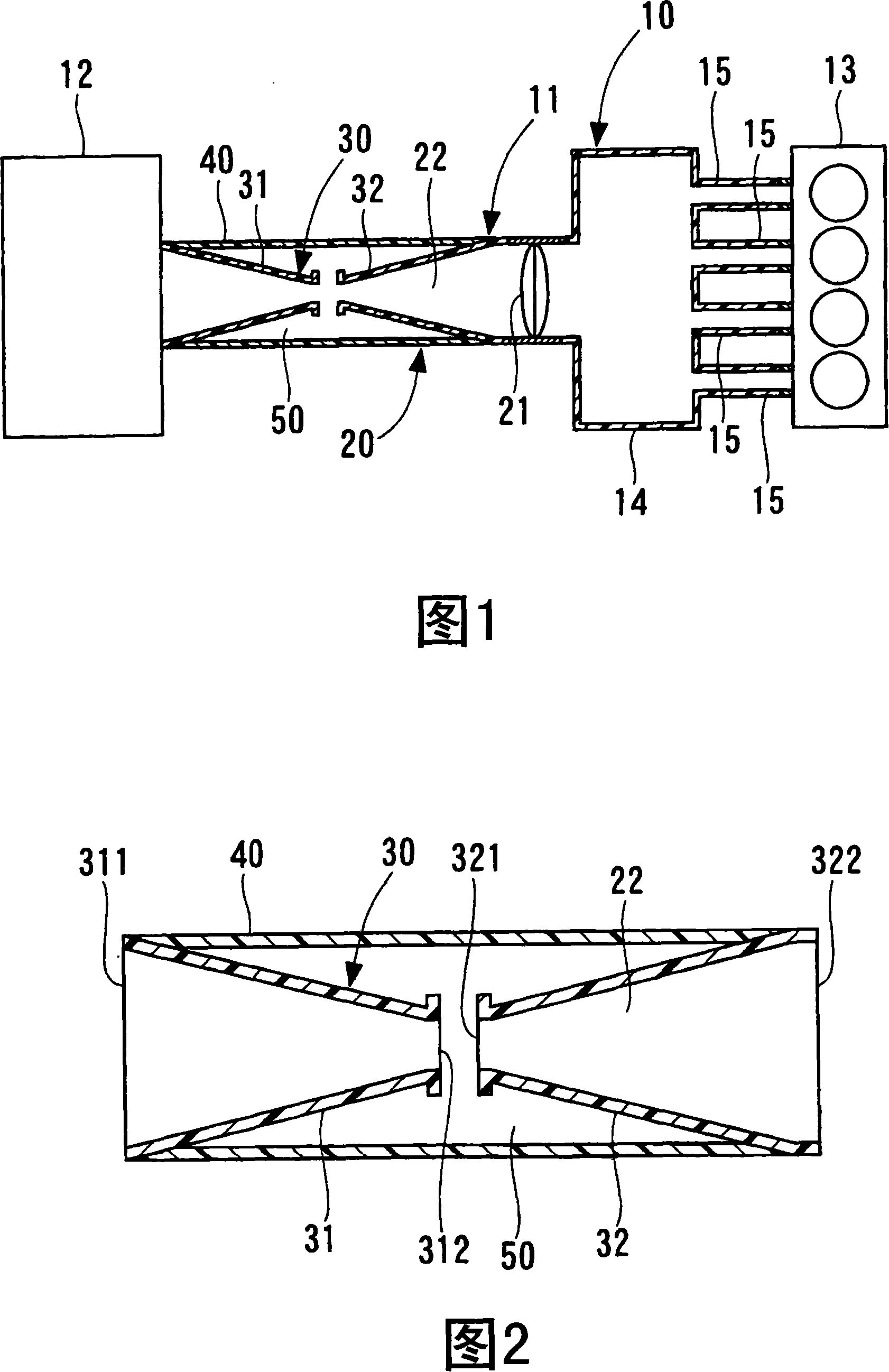
[0014] FIG. 1 shows an air intake system to which an air intake device according to a first embodiment of the present invention is applied.
[0015] As shown in FIG. 1 , an intake system 10 includes an intake device 11 , an air cleaner 12 and a gasoline engine (hereinafter referred to as an engine) 13 as an internal combustion engine. The air intake device 11 has a surge tank 14 . An intake manifold 15 branches off from the surge tank 14 . The intake manifold 15 is branched according to the number of cylinders of the engine 13, and each intake manifold 15 is connected to a corresponding one of the cylinders.
[0016] The air cleaner 12 is arranged at the end of the intake device 11 opposite to the other end where the engine 13 is arranged. The air cleaner 12 accommodates an air cleaning member (not shown) inside the air cleaner 12 . When the air sucked into the engine 13 flows through the air cleaner 12, impurities are removed from the air. The air sucked into the engine 1...
no. 2 approach
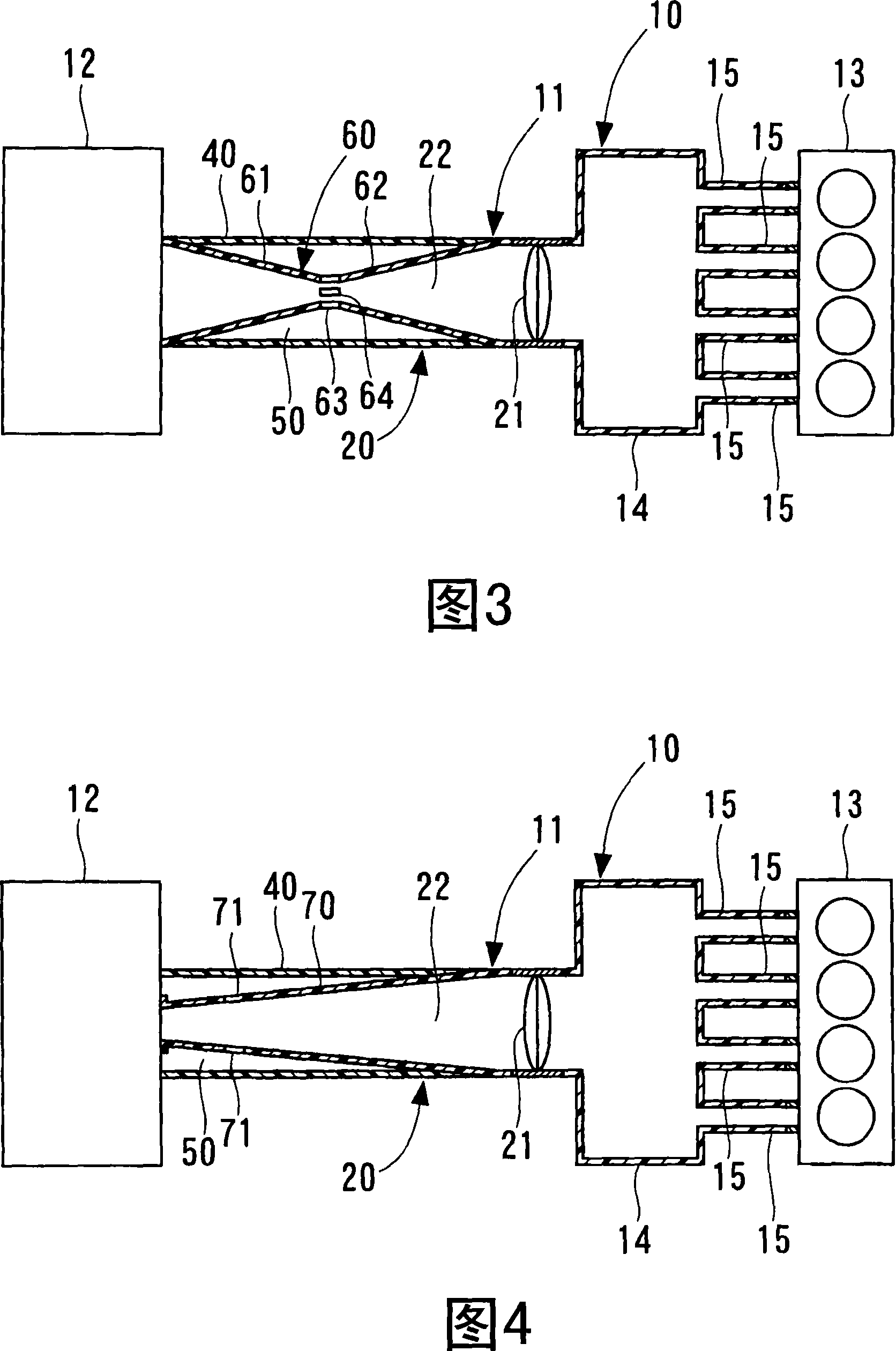
[0029] FIG. 3 shows an air intake system to which an air intake device according to a second embodiment of the present invention is applied.
[0030] In the second embodiment, the inner tube element 60 is formed from one element. That is, the inner pipe member 60 has a first pipe portion 61 , a second pipe portion 62 and a small diameter portion 63 . The small-diameter portion 63 is provided at the center thereof in the axial direction of the inner pipe member 60 . The inner pipe member 60 has a first pipe portion 61 extending from the end of the inner pipe member 60 on the air cleaner 12 side toward the small diameter portion 63 and a first pipe portion 61 extending from the small diameter portion 63 toward the inner pipe member 60 on the surge tank 14 side. The second tube portion 62 extends at the end.
[0031] The first pipe portion 61 is formed in a frustoconical shape in a tubular form whose diameter gradually decreases from the end portion on the side of the air clean...
no. 3 approach
[0034] FIG. 4 shows an air intake system to which an air intake device according to a third embodiment of the present invention is applied.
[0035] In the third embodiment, the diameter of the inner diameter member 70 increases from its end on the air cleaner 12 side toward the other end on the surge tank 14 side. That is, the intake device 11 has only elements corresponding to the second inner pipe element 32 and does not have elements corresponding to the first inner pipe element 31 in the first embodiment. The sound of the intake air flowing in the intake passage 22 is reduced in a wide frequency range by the diffusion effect of the inner pipe member 70 whose diameter increases from the air cleaner 12 side to the surge tank 14 side. Therefore, by providing the inner pipe member 70 having the shape of the third embodiment, intake noise can be reduced.
[0036] The outer circumferential side of the inner pipe member 70 is covered by the outer pipe member 40 . Thus, the res...
PUM
 Abstract
Description
Claims
Application Information