Fan and blade wheel thereof

A technology of fan blades and impellers, which is applied in the field of multi-blade fans and their impellers, which can solve the problems of poor airflow utilization efficiency and excessive fan power consumption, so as to improve airflow utilization efficiency, enhance working ability, and avoid The effect of reflow

Active Publication Date: 2008-01-30
DELTA ELECTRONICS INC
View PDF0 Cites 1 Cited by
  • Summary
  • Abstract
  • Description
  • Claims
  • Application Information

AI Technical Summary

Problems solved by technology

However, when the airflow passes through the impeller 10, the airflow is affected by the ring 11, resulting in poor airflow performance near the ring 11, and the backflow of the airflow after the airflow flows out of the impeller 10, which in turn increases the power consumption of the fan

Method used


Image

  • Fan and blade wheel thereof
  • Fan and blade wheel thereof
  • Fan and blade wheel thereof

Examples


Embodiment Construction

[0022] A fan and its impeller according to preferred embodiments of the present invention will be described below with reference to related drawings, wherein the same components will be described with the same reference symbols.

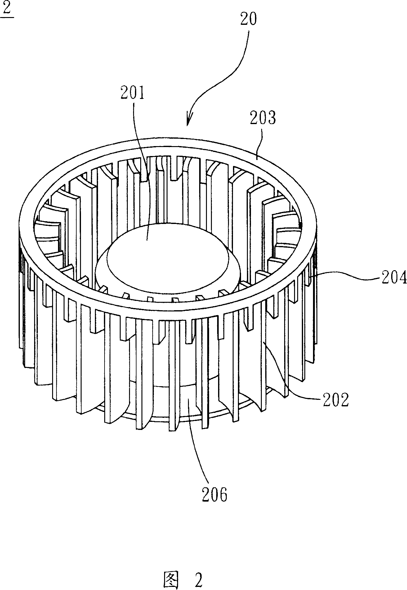
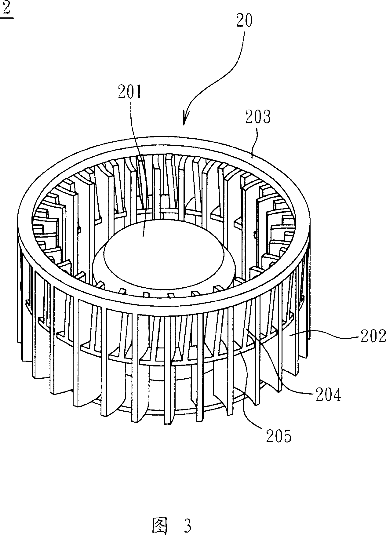
[0023] Please refer to FIG. 2 , a fan 2 according to a preferred embodiment of the present invention includes an impeller 20 and a motor 21 . In this embodiment, the fan 2 is a centrifugal fan, but this is only for example and not limited thereto.

[0024] The impeller 20 includes a hub 201 , a plurality of first fan blades 202 , at least one reinforcement member 203 and a plurality of second fan blades 204 . The first fan blades 202 are arranged around the hub 201, wherein the first fan blades 202 can be integrally formed with the hub 201; and the motor can be accommodated in the hub 201 to connect and drive The impeller 20 rotates.

[0025] The reinforcing member 203 connects the first fan blades 202 to strengthen the structure of the first fan b...


PUM


Abstract

The invention discloses an impeller comprising a wheel hub and a plurality of a first fan flabellum and a plurality of a second fan flabellum. Each of the first fan flabellum is arranged around the wheel hub and each of the second fan flabellum is arranged between the first fan flabellum. In addition the length of the second fan flabellum is less than that of the first fan flabellum.

Description

technical field [0001] The invention relates to a fan and its impeller, in particular to a multi-blade fan and its impeller. Background technique [0002] With the rapid development of electronic products towards high performance, high frequency, high speed and thinness, the heating temperature of electronic products is getting higher and higher, which is prone to instability and affects product reliability. Therefore, heat dissipation has become an important aspect of electronic products. one of the important subjects. [0003] It is a common structural arrangement to use a fan as a cooling device. Please refer to FIG. 1 . An impeller 10 of an existing centrifugal fan includes a plurality of fan blades 101 and a hub 102, and the fan blades 101 are arranged around the hub 102. The hub 102 is used to accommodate a motor (not shown in the figure), and the impeller 10 is driven to rotate by the motor. [0004] As the demand for heat dissipation is increasing, the requirements...

Claims


Application Information

Patent Timeline
IPC IPC(8): F04D29/30
Inventor 蒋宸谟篮重凯陈弘琪
Owner DELTA ELECTRONICS INC
Why Eureka
Try Eureka