Setting device, component mounting system, program and calculating method

A technology for setting devices and installing components, applied in computing, electrical components, electrical components, etc., can solve the problem of longer component installation time, and achieve the effect of shortening the installation time and reducing the amount of movement

Inactive Publication Date: 2008-01-30
HITACHI HIGH TECH INSTR CO LTD
View PDF1 Cites 5 Cited by
  • Summary
  • Abstract
  • Description
  • Claims
  • Application Information

AI Technical Summary

Problems solved by technology

[0005] In the technique described in Japanese Patent Laid-Open No. 8-32294, regarding the angle at which components are mounted on the substrate, since the mounting angle of the components is determined in a

Method used


Image

  • Setting device, component mounting system, program and calculating method
  • Setting device, component mounting system, program and calculating method
  • Setting device, component mounting system, program and calculating method

Examples


Embodiment Construction

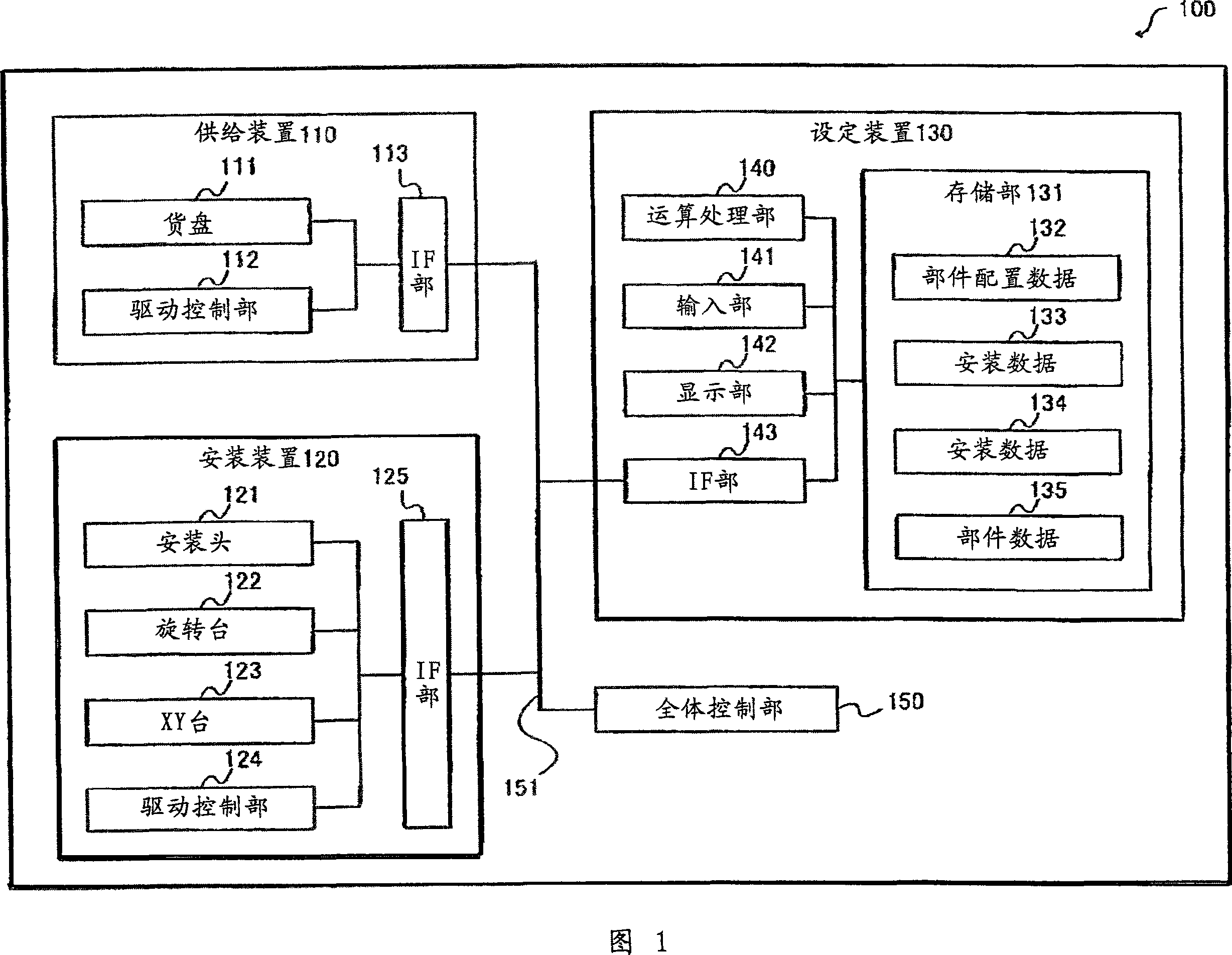
[0025] Fig. 1 is a schematic diagram of a component mounting system 100 according to a first embodiment of the present invention.

[0026] As shown in the figure, the component mounting system 100 has a supply device 110 , a mounting device 120 , a setting device 130 , and an overall control unit 150 , and these are connected to each other via a bus 151 .

[0027] The supply device 110 has a pallet 111 , a drive control unit 112 , and an IF unit 113 .

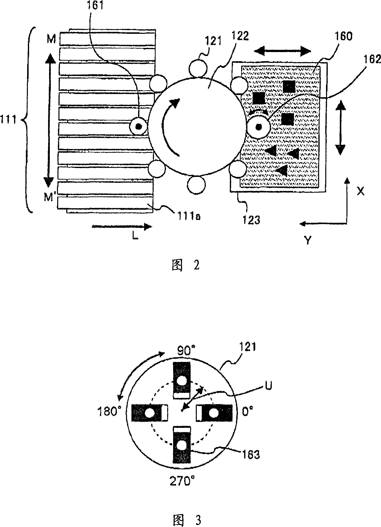
[0028] Pallet 111, as shown in FIG. 2 (top view of pallet 111, mounting head 121, rotary table 122, and XY table 123), holds components to be mounted on base plate 160 on a feeder belt, and a plurality of configurations are transported to after use. The tape feeder 111a is attached to the position where the mounting head 121 is sucked.

[0029] In addition, one kind of parts is respectively held in the same posture on one tape feeder 111a by placing the pallet 111 in a direction (M direction or M' direction) perpendicular to t...


PUM


Abstract

The present invention relates to a setting device, a component mounting system, a program, and a calculation method. An object of the present invention is to provide a technique for changing a component mounting angle in order to reduce a relative movement amount between a mounting head and a substrate. The solution is to determine the components whose mounting angles can be changed by using the information stored in the mounting data storage area and the component data storage area in accordance with the predetermined mounting order of the components, and calculate the angle of change of the determined components in each mounting angle. The installation time of the installation path of the installation angle determines the installation path with the shortest installation time.

Description

technical field [0001] The present invention relates to a technique of mounting components on a substrate. Background technique [0002] In a conventional component mounting device for mounting electronic components on a circuit board, the component held in the tape feeder of the component supply device is sucked by the suction nozzle of the mounting head and transported to a predetermined position on the circuit board. Install. [0003] In such a component mounting apparatus, the mounting head is formed in a disc shape, and suction nozzles are provided at positions spaced apart from the center of the mounting head. Then, by rotating the mounting head around its center at a predetermined angle, the angle of the component sucked by the suction nozzle can be changed and mounted on the circuit board. [0004] In such a component mounting device, in order to shorten the component mounting time, it is known to rotate the mounting head in a direction in which the rotation angle ...

Claims


Application Information

Patent Timeline
IPC IPC(8): H05K13/04H05K13/08B23P19/00G06F17/00
CPCH05K13/0413H05K13/0853Y10T29/4913Y10T29/53174
Inventor 智田崇文阿蒂拉·伦杰尔五十岚健山口晴彦冈本学泉原弘一
Owner HITACHI HIGH TECH INSTR CO LTD
Why Eureka
Try Eureka