Rotation angle detection device and rotation angle correction method

A technology of rotation angle detection and rotation angle, which is applied in the direction of measuring devices, electric devices, electric steering mechanisms, etc., can solve the problems of reduced accuracy of rotation angle detection, difficulty with belts, and unsuitability for absolute rotation angle detection, etc., to achieve improved rotation The effect of angle detection accuracy and high resolution

Inactive Publication Date: 2008-01-30
PANASONIC CORP
View PDF2 Cites 49 Cited by
  • Summary
  • Abstract
  • Description
  • Claims
  • Application Information

AI Technical Summary

Problems solved by technology

Moreover, since the rotation of the encoder plate and the rotation of the shaft are realized through gears, it is a little difficult to improve the detection accuracy through backlash, etc.
Moreover, since the rotation angle detection device can only be used when detecting relative rotation angles, it is not suitable for detection of absolute rotation angles.
[0006] Furthermore, in the above-mentioned rotation angle detection device, there is a problem that the detection accuracy of the rotation angle of the detected shaft is lowered due to the alignment accuracy or eccentricity of the gears, the detection error of the rotation angle detection unit, and the like.

Method used


Image

  • Rotation angle detection device and rotation angle correction method
  • Rotation angle detection device and rotation angle correction method
  • Rotation angle detection device and rotation angle correction method

Examples


Embodiment approach 1

[0127] Hereinafter, Embodiment 1 of the present invention will be described using FIGS. 1 to 7 .

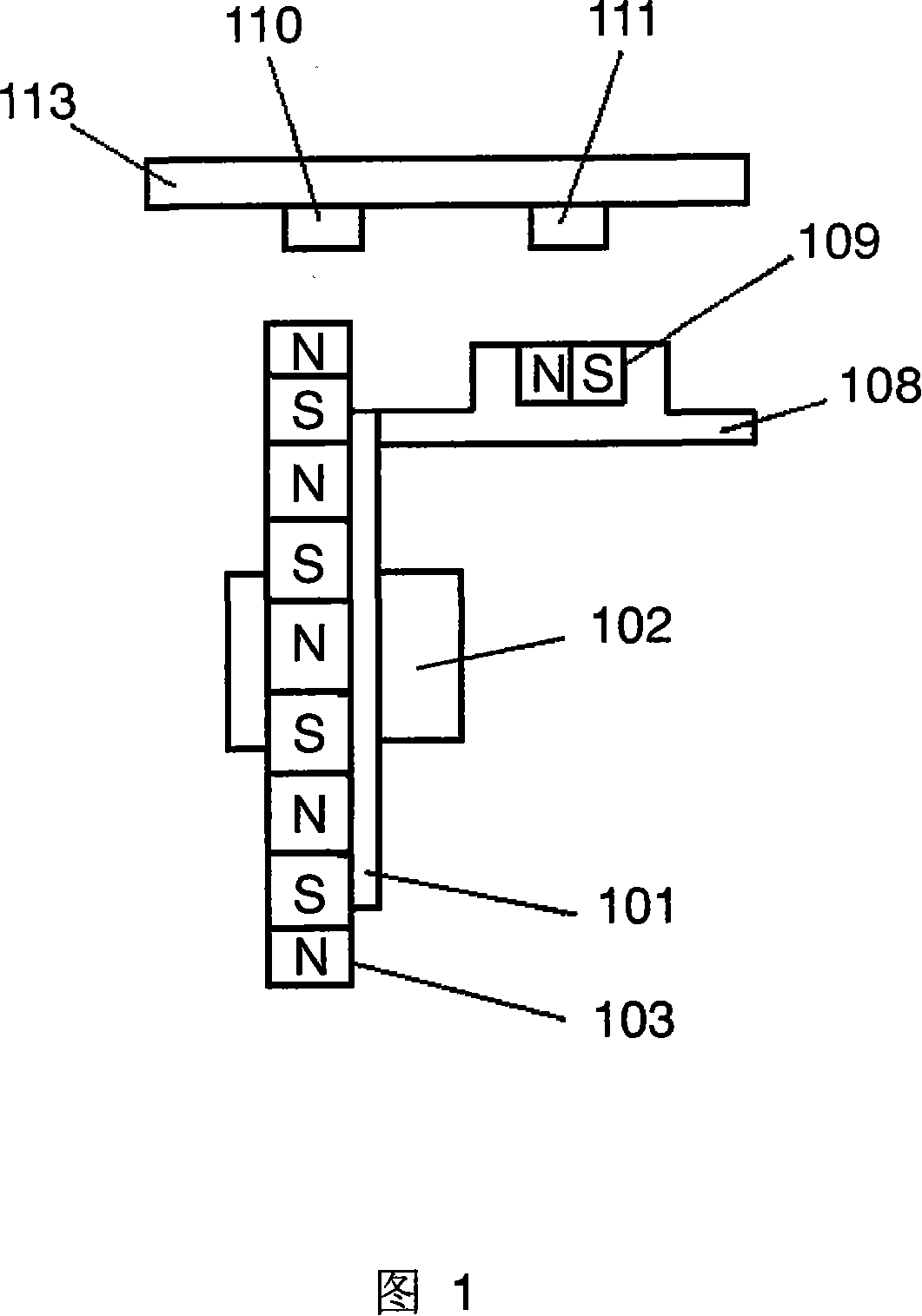
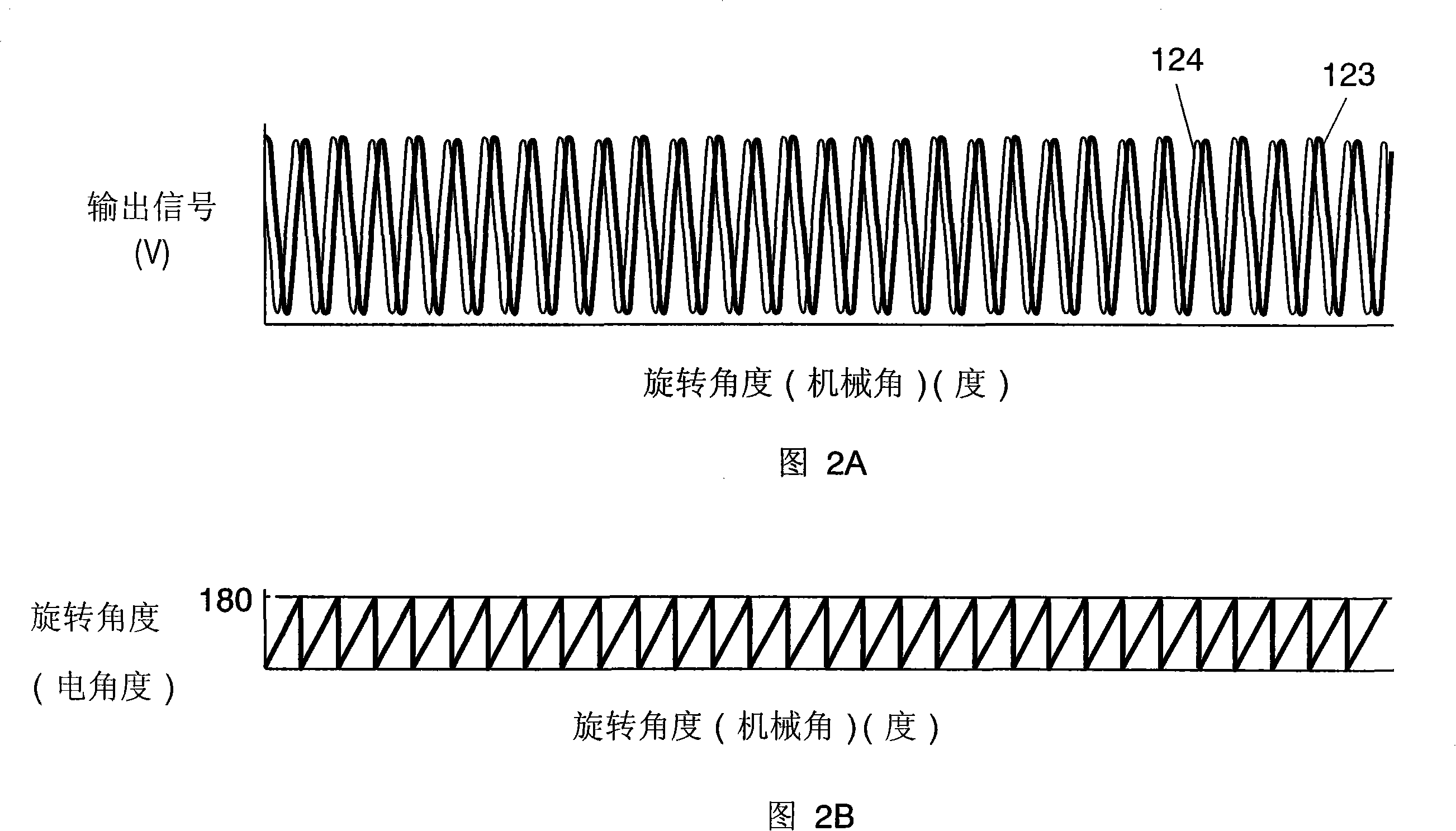
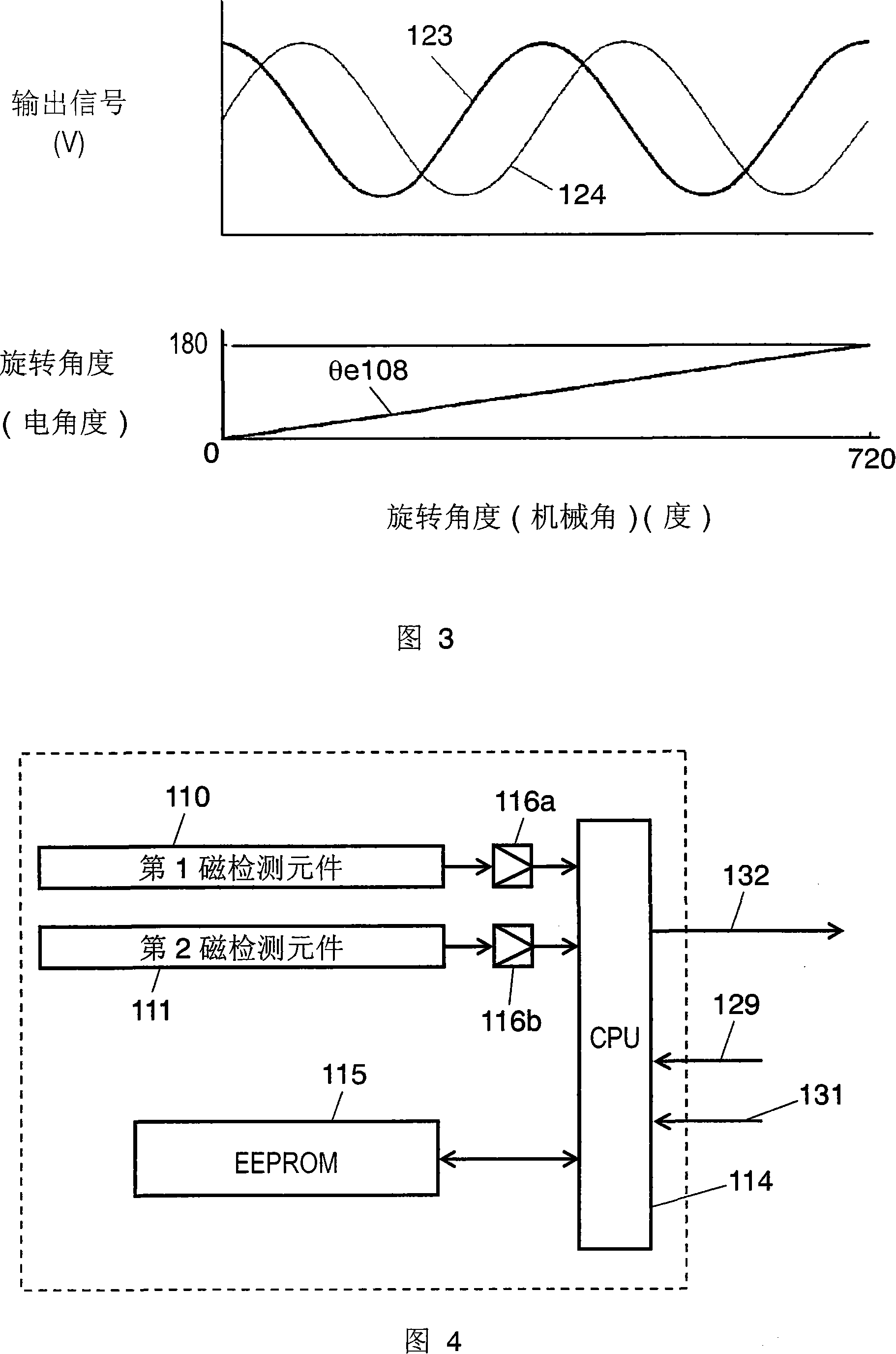
[0128] 1 is a diagram showing a basic configuration of an absolute rotation angle detection device according to Embodiment 1 of the present invention, FIG. 2 is a diagram showing a rotation angle detection signal of a first magnetic detection element, and FIG. 3 is a diagram showing a rotation angle detection signal of a second magnetic detection element. Signal diagram, Figure 4 is a circuit block diagram of the absolute rotation angle detection device. Fig. 5 is a diagram showing the ideal value and actual value of the absolute rotation angle of the first and second rotating bodies, Fig. 6 is a diagram showing the rotation angle calculation output signal and the absolute rotation angle in the CPU, and Fig. 7 shows the first and second rotating bodies 2 The output signal diagram of the magnetic detection element.

[0129] In FIG. 1 , a first rotating body 101 is a rotating body...

Embodiment approach 2

[0148]Embodiment 2 will be described using FIGS. 8A to 14 . 8A, FIG. 8B and FIG. 8C are basic configuration diagrams of a rotation angle detection device according to Embodiment 2, FIG. 9 is a circuit block diagram of the rotation angle detection device, and FIGS. 10A and 10B are diagrams showing output signals of the first detection unit, 11A and FIG. 11B are diagrams showing the output signal of the third detection unit, and FIG. 12A and FIG. 12B are diagrams showing the output signal of the fourth detection unit. FIG. Figure 14 is an explanatory diagram for explaining a method for preventing occurrence of rotation angle detection errors.

[0149] In FIGS. 8A to 8B , the input shaft 204 is fitted with the first rotating body 203 capable of rotating multiple times. The outer peripheral surface of the first target 205 held by the first rotating body 203 has magnetic poles whose polarities are alternately magnetized at equal intervals. The second rotating body 210 has a gear ...

Embodiment approach 3

[0183] Next, Embodiment 3 of the present invention will be described using FIGS. 15 to 23 . In particular, Embodiment 3 relates to a high-precision rotation angle detection device for correcting a mechanical error of a gear or an electronic error of a rotation angle detection unit, and a method for correcting the rotation angle.

[0184] 15 is a configuration diagram of a rotation angle detection device according to Embodiment 3 of the present invention. A multi-pole magnetic ring 302 serving as a target is connected to the detected shaft 301 , and a first rotation angle detection unit 303 is arranged at a position facing the multi-pole magnetic ring 302 . A worm wheel 304 is connected to the detected shaft 301 , and a gear 305 meshes with the worm wheel 304 . A magnet 306 is arranged at the center of the gear 305 , and a second rotation angle detection unit 307 for detecting a rotation angle is arranged at a position facing the magnet 306 . The motor 309 is installed on the...


PUM


Abstract

There is provided a device for detecting an absolute rotation angle of multi-rotation with high accuracy and high resolution by using a target connected to the rotation angle and having an outer circumference to which magnetic poles of alternate polarities are magnetized. The device includes: a first rotor (101) holding the target (103) connected to an input axis (102) and having an outer circumference to which magnetic poles of alternate polarities are magnetized at an identical interval and having multi-rotatable gear; a second rotor (108) connected tot he gear of the first rotor (101), rotated at a low speed by the first rotor (101), and having a magnet (109) at the center portion; a first detection unit (110) and a second detection unit (111) for detecting the rotation angles of them. With a simple configuration, it is possible to detect an absolution rotation angle with a high accuracy and a high resolution.

Description

technical field [0001] The present invention relates to a rotation angle detection device used in a vehicle body control system, etc., and more particularly to a rotation angle detection device for detecting an absolute rotation angle of a multi-rotatable steering wheel and a method for correcting the rotation angle. Background technique [0002] Fig. 26 shows a conventional rotation angle detecting device. The gear unit 38 is attached to a rotation shaft (not shown) whose rotation angle is to be detected by engaging a spring 39 . The gear part 38 meshes with a gear part 41 on which an encoder plate 40 magnetized with a plurality of magnetic poles is mounted on the outer peripheral end surface, and the magnetic poles provided on the encoder plate 40 move with the rotation of the rotating shaft to be detected. The number of the magnetic poles is counted by the detection element 42 provided facing the outer peripheral end surface, thereby detecting the rotation angle. [000...

Claims


Application Information

Patent Timeline
Patent Type & Authority Applications(China)
IPC IPC(8): G01B7/30B62D5/04
Inventor 植平清孝御池幸司一宫礼孝笹之内清孝三户宏一
Owner PANASONIC CORP
Why Eureka
Try Eureka