Eureka AIR delivers breakthrough ideas for toughest innovation challenges, trusted by R&D personnel around the world.

Backlight drive having isolated form power factor correcting structure and control circuit thereof

A backlight drive and control circuit technology, applied to static indicators, instruments, etc., can solve the problems of increasing the number of optical coupling components and threats to user safety

Inactive Publication Date: 2008-02-06
ZIPPY TECH
View PDF0 Cites 5 Cited by
  • Summary
  • Abstract
  • Description
  • Claims
  • Application Information

AI Technical Summary

Problems solved by technology

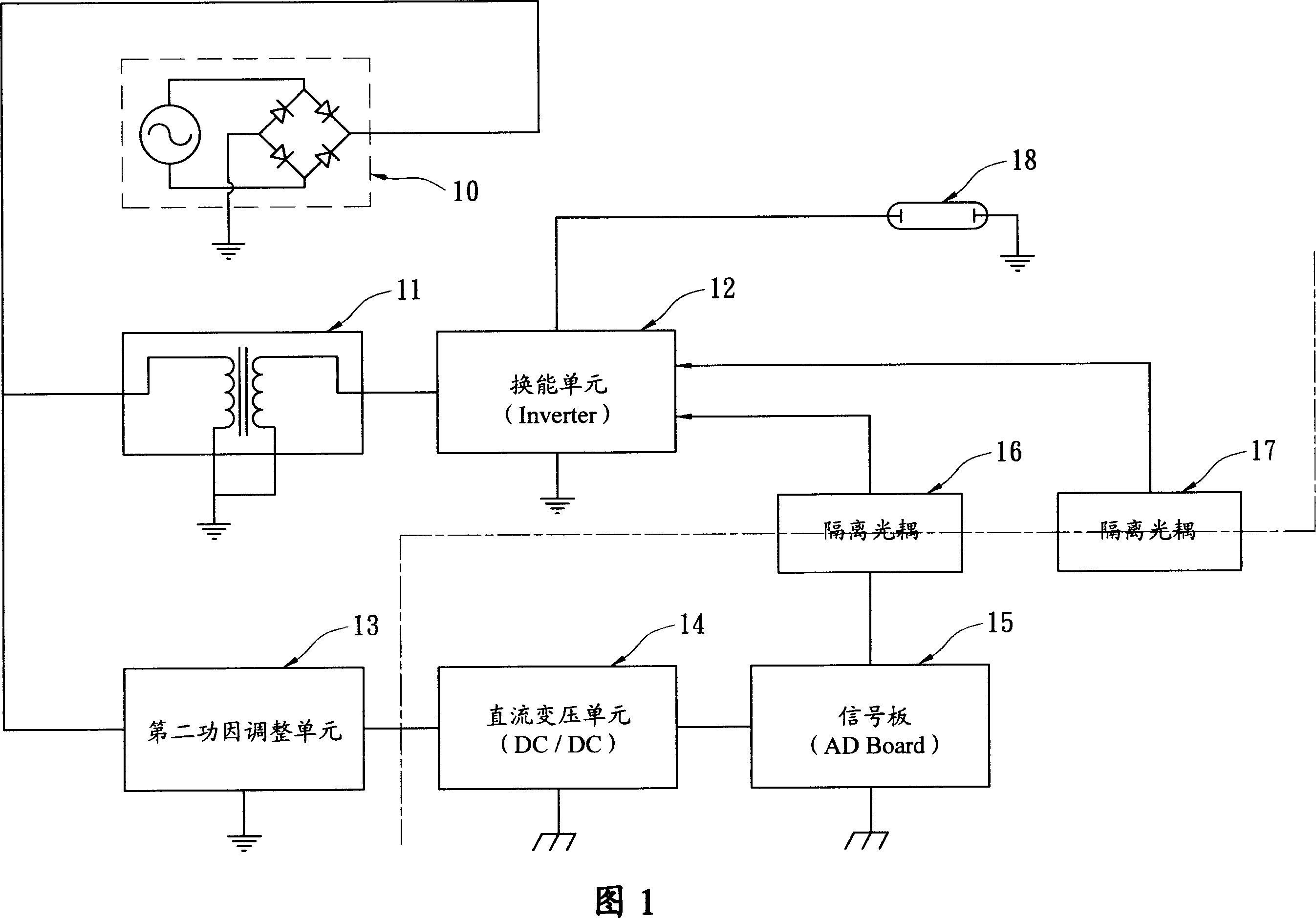
[0004] Since the transduction unit 12 and the aforementioned first power factor adjustment unit 11 in the conventional technology have a common ground (high-voltage power supply ground) circuit structure, the signal board 15 and the transduction unit 12 have an isolated circuit structure that is not commonly grounded. Therefore, the control signals in the signal board 15 (such as controlling the brightness / darkness (On / Off) of the backlight or adjusting the brightness of the backlight (Dimming)) will not be directly connected to the transducer unit 12, so the way of isolating optocouplers 16 and 17 must be used Control the energy conversion unit 12 (including dimming and on / off control of the backlight element), however, this method of transmitting control signals by isolating the optocouplers 16 and 17 will inevitably cause optical coupling increase in the number of components; on the other hand, since the power factor adjustment unit (including the first power factor adjustment unit 11 and the second power factor adjustment unit 13) adopts a common ground design with the power supply end, but there is no primary and secondary area separated, thus easily posing a threat to the safety of users

Method used


Image

  • Backlight drive having isolated form power factor correcting structure and control circuit thereof
  • Backlight drive having isolated form power factor correcting structure and control circuit thereof

Examples


Embodiment Construction

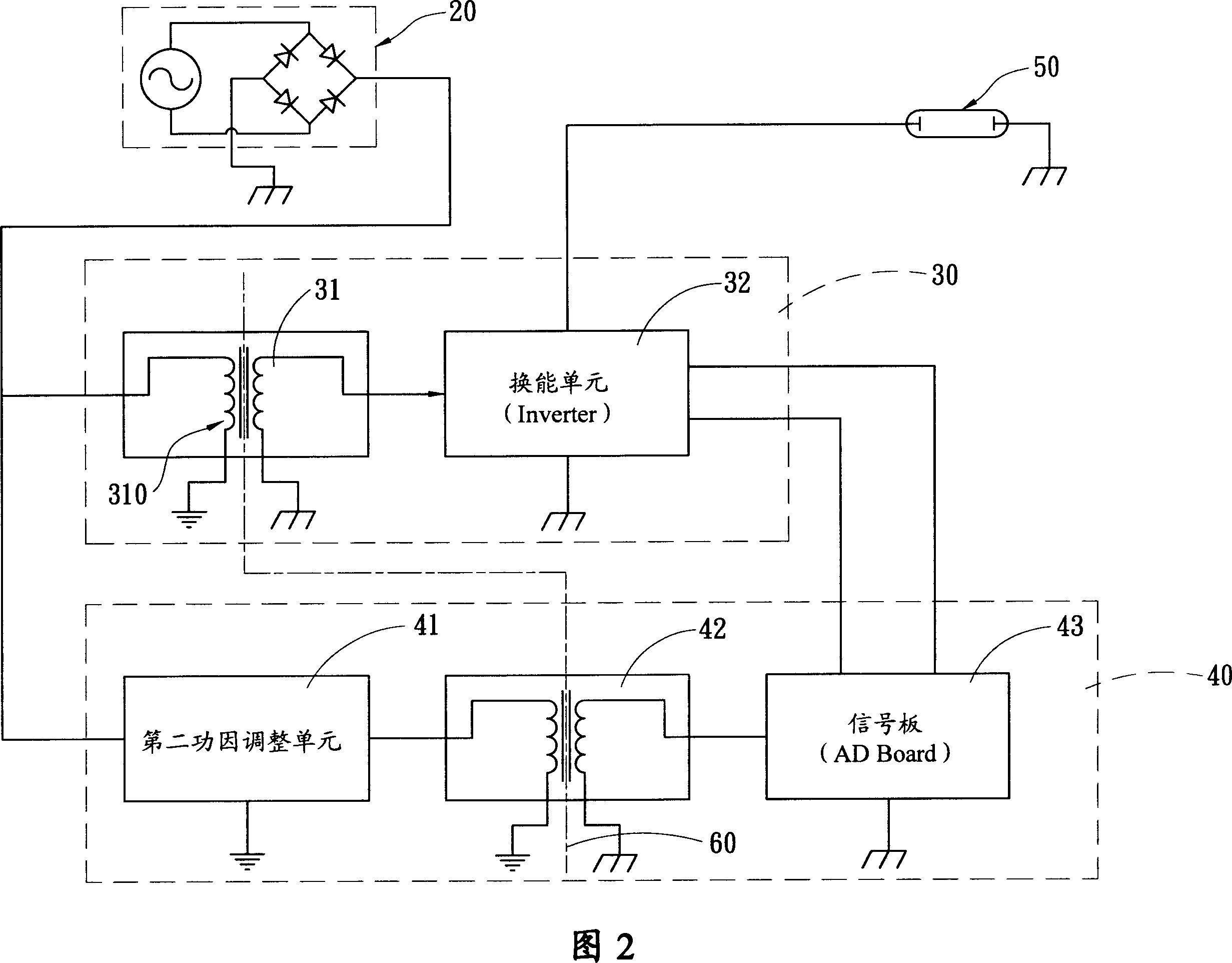
[0012] The circuit architecture of the preferred embodiment of the present invention, as shown in FIG. 2, includes:

[0013] Power Stage 20 (Power Stage) is used to provide power, which converts the city power (AC power) into the DC power required by the device. The power specifications of the city power are different according to the power specifications of each country (for example, AC-110V or AC-220V). Generally speaking, the so-called power stage 20 can be equipped with an electromagnetic interference filter unit (EMI) and a bridge rectifier composed of diodes, which are used to filter and rectify the alternating current and output a full / half wave DC power supply (the electromagnetic interference filter unit (EMI) among them needs to be determined according to the specifications of the power system in various countries);

[0014] The driver stage (Driver Stage) 30 has a first power factor adjustment unit 31 for adjusting the power factor of the power supply and outputting a m...


PUM


Abstract

The present invention relates to a backlight driving and controlling circuit with an isolating-type power factor correction configuration, and comprises a power stage for providing the power supply; a driver stage with a first power factor adjustment unit for adjusting the power factor of the power supply and outputting DC source, and with a conversion unit for converting a medium voltage DC power into a high power output to further drive the back-light light emitting elements to work; and a control / dimming stage with a second power factor adjustment unit and a DC variable voltage unit and an AD board arranged on the secondary of the DC variable voltage unit and connected with the ground commonly with the conversion unit. The present invention adopts the design of electric isolation and circuit configuration of communal connection with the ground, which forms the electric isolation between the power factor adjustment unit and the power stage, and allows the AD board to directly control / dim the above-mentioned conversion unit of the diver stage, thereby changing the working state of back-light light emitting elements.

Description

Technical field [0001] The invention relates to a drive and control circuit for an electronic load, in particular to a backlight drive and control circuit with an isolated power factor correction structure. Background technique [0002] It is known that the driving and control circuit architecture used to control the backlight element of a display (such as a liquid crystal display). As shown in FIG. 1, the alternating current (AC) provided by the power supply terminal 10 is filtered and rectified and then supplied to two parts respectively. One part is used to drive the load (such as cold cathode fluorescent tubes, CCFL and other light-emitting elements), and the second part is to supply the power required by the control circuit (such as the control circuit board, AD Board). [0003] The circuit architecture of the first part includes: a first power factor adjustment unit 11, connected to the power supply terminal 10, used to adjust the power factor of the power supply and output...

Claims


Application Information

Patent Timeline
IPC IPC(8): G02F1/133G09G3/34
Inventor 周进文郑英男钟金标
Owner ZIPPY TECH
Why Eureka
Eureka Blog
Learn More