Fire flooding oil extraction method for vertical well gas-injection horizontal well oil extraction

A technology for steam injection wells and horizontal wells, which is applied in wellbore/well components, production fluids, earthwork drilling and production, etc. It can solve intra-layer contradictions, plane contradictions, low-permeability lithology, unsatisfactory oil displacement effects, and affect recovery Efficiency and other issues, to achieve quick results, increase the ultimate recovery, and improve the effect of recovery

Inactive Publication Date: 2008-02-13
尤尼斯油气技术(中国)有限公司
View PDF0 Cites 34 Cited by
  • Summary
  • Abstract
  • Description
  • Claims
  • Application Information

AI Technical Summary

Problems solved by technology

Although a small amount of underground crude oil can be recovered by adopting thermal recovery methods such as steam flooding, steam huff and puff, burning oil layers and heavy oil fire flooding, steam injection in vertical wells, and oil production in vertical wells, due to conflicts between heavy oil layers and intralayer conflicts , Plane contradiction, uneven lithology of heavy oil formations, and lithological high-permeability bands, so it is difficult to use steam to heat the wellbore and use SIGD oil recovery method to overcome the phenomenon of gas stringing on the rock formation plane during steam injection, steam is easy Flowing in layers with higher permeability, the low-per

Method used


Image

  • Fire flooding oil extraction method for vertical well gas-injection horizontal well oil extraction

Examples


Embodiment 2

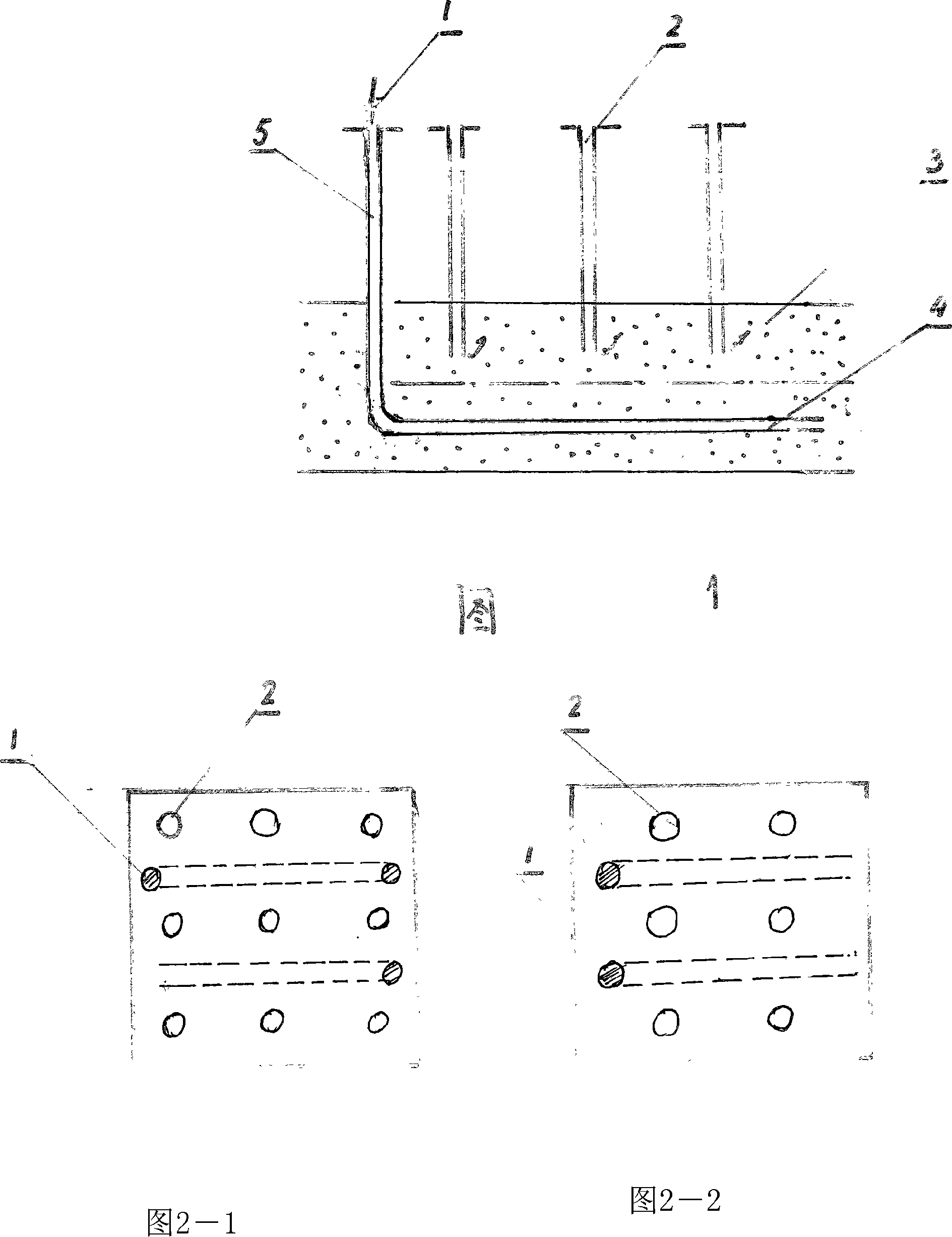
[0024] The ignition method of the fire flooding oil production method for vertical well steam injection and horizontal well oil production is steam injection to stimulate ignition, application number: "2005101308608", which is a steam injection well to inject steam and air into the heavy oil in the well to ignite the oil layer After heating, the heat generated by the fluid and CO 2 The gas accumulates at the top of the oil layer, forming an internal gas cap and pressing on the heavy oil layer, forcing the crude oil to flow into the horizontal well for production under its own weight. Since the horizontal wellbore crosses the heavy oil layer laterally, the steam injection production is not controlled by lithology. It can effectively improve the ultimate recovery factor.

Embodiment 3

[0026] In order to achieve the best recovery rate, it is the key to choose the distance between the steam injection well and the oil production well of the vertical shaft reasonably. For this reason, the distance between the steam injection well 2 in the vertical shaft is 700 meters, and the well distance between the oil production wells is 1 km. The oil production wells can also choose four vertical shaft steam injection wells, one oil production well and eight vertical shaft steam injection wells, and three oil production wells can be used as a well group to carry out fire flooding oil production.


PUM

PropertyMeasurementUnit
Viscosity valueaaaaaaaaaa
Densityaaaaaaaaaa

Abstract

The invention relates to a viscous oil exploitation method, in particular to a fire flooding oil exploitation method used for gas injection by a vertical well and oil exploitation by horizontal well. The invention adopts the compound well-layout manner of steam injection by vertical wells and oil exploitation by horizontal wells, which means that six vertical wells are for gas injection and two oil exploitation wells for oil exploitation, or nine vertical wells for gas injection and three oil exploitation wells for oil exploitation. When the wells are drilled, the vertical wells are drilled until they reach the half thickness of an oil layer, and gas is injected above the half thickness of the oil layer. The horizontal wells are under the half thickness of the oil layer. The gas-cap pressure produced by burning of the gas-injected oil layer of the above vertical wells presses the crude oil of the lower part, while the crude oil flows to the horizontal well sections by the self-gravity and then is exploited from the exploitation wells . The invention overcomes the shortcoming that gas channeling can be easily formed horizontally along an oil layer in a high-penetration passage inside the oil layer, and promotes the final recovery rate of the oil layer through fire flooding by fifteen percent.

Description

Technical field: [0001] The invention relates to a heavy oil production method; in particular, a fire flooding oil production method used for oil production in vertical wells with steam injection and horizontal wells. Background technique: [0002] Heavy oil is an important part of petroleum hydrocarbon energy, and has a huge potential several times higher than conventional crude oil resources. my country is rich in heavy oil resources and widely distributed. Liaohe Oilfield is the main heavy oil development area in my country. There are many types of reservoirs and the burial depth varies greatly. (See Petroleum Industry Press, Han Xianqing Enhanced Oil Recovery Basis 1993 131 157-160) In addition, due to the high viscosity and high density of heavy oil, the flow resistance during production is large, the displacement efficiency and volumetric oil efficiency are also low, and it is difficult to use conventional method to mine. Although a small amount of underground crude ...

Claims


Application Information

Patent Timeline
IPC IPC(8): E21B43/24
Inventor 张吉林邓惠荣祝学江
Owner 尤尼斯油气技术(中国)有限公司
Why Eureka
Try Eureka