
Electronic device

A technology of electronic devices and solar cells, applied in identification devices, circuits, photovoltaic power generation, etc., can solve problems such as difficult current control

Inactive Publication Date: 2008-02-13
SONY GRP CORP
View PDF1 Cites 7 Cited by
  • Summary
  • Abstract
  • Description
  • Claims
  • Application Information

AI Technical Summary

Problems solved by technology

[0006] However, in the above-mentioned conventional method, since the power generation efficiency fluctuates depending on the content displayed on the electronic paper, it is difficult to perform current control.

Method used


Image

  • Electronic device
  • Electronic device
  • Electronic device

Examples


Embodiment Construction

[0025] Hereinafter, specific embodiments to which the present invention is applied will be described in detail with reference to the drawings.

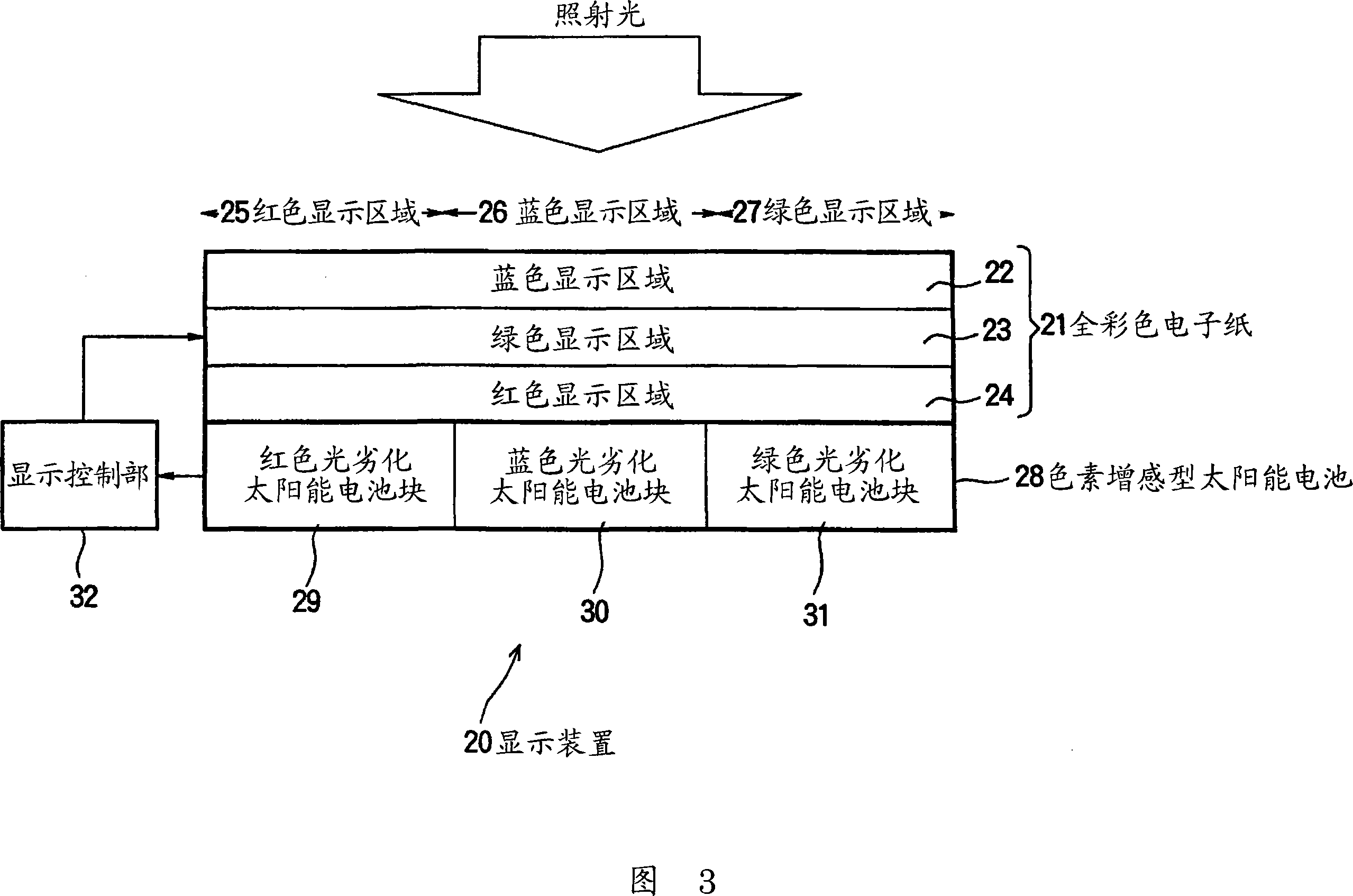
[0026] FIG. 3 shows a first configuration example of a display device as an embodiment of the present invention. The display device 20 is composed of a full-color electronic paper 21, a dye-sensitized solar cell 28, and a display control unit 32; the full-color electronic paper 21 displays characters, graphics, etc.; The backside of the full-color electronic paper 21 converts the irradiated light into electricity; the display control unit 32 uses the power generated by the dye-sensitized solar cell 28 as a power source to control the display of the full-color electronic paper 21 .

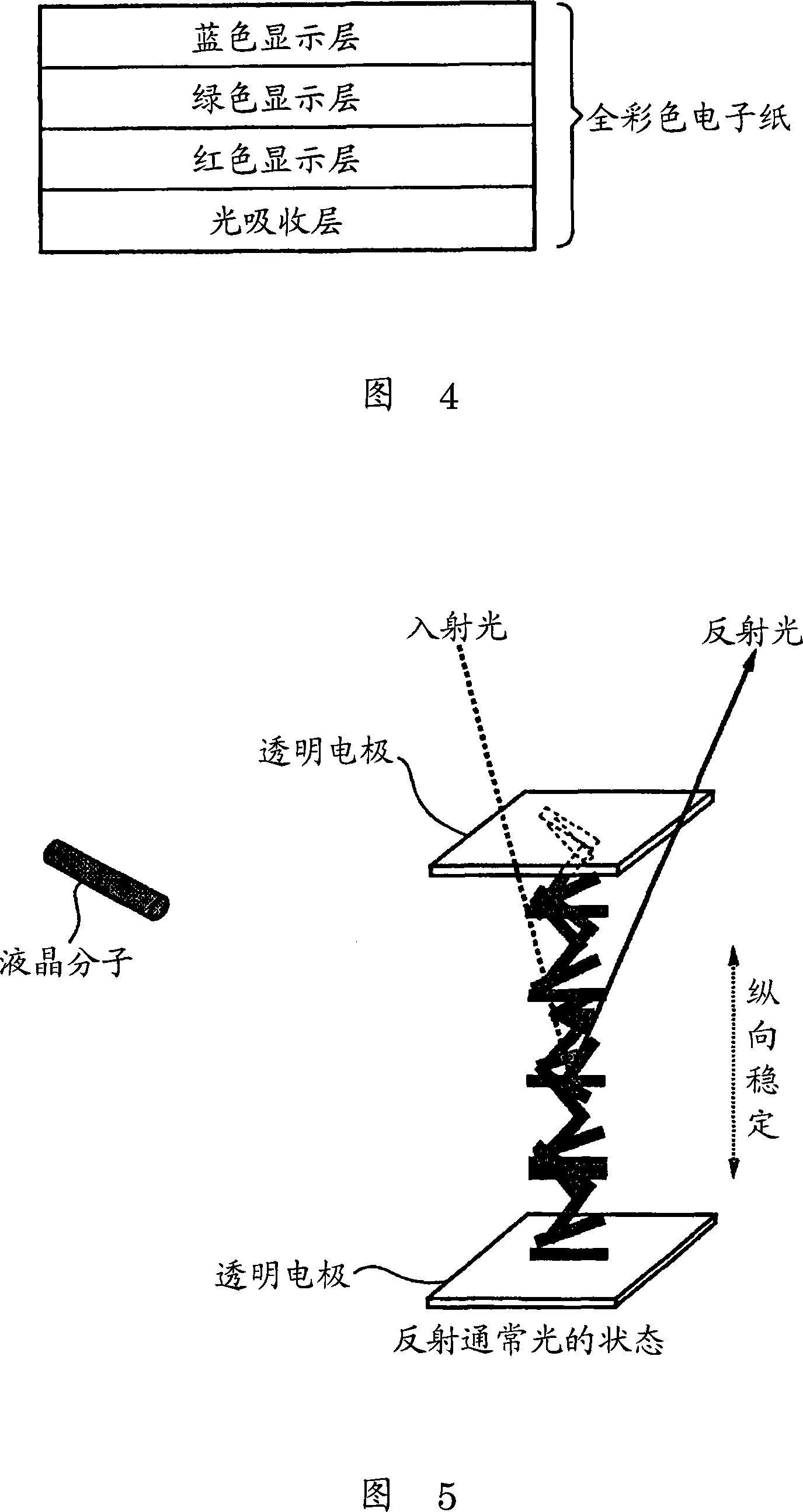
[0027] Here, a general full-color electronic paper using cholesteric liquid crystals will be described with reference to FIG. 4 . Common full-color electronic paper consists of a blue display layer, a green display layer, a red display layer and a light-a...


PUM


Abstract

The present invention provides an electric device. In the device the display and the solar battery are stacked while the displaying content of the display does not affect the generating efficiency of the solar battery. The light which transmits full-color electronic paper (21) except for the red light is always irradiated to the red light deteriorating solar battery block (29) of the dye-sensitized solar cell (28). Otherwise, the light which transmits full-color electronic paper (21) except for the blue light is always irradiated to the blue light deteriorating solar battery block (30). Besides, the light which transmits full-color electronic paper (21) except for the green light is always irradiated to the green light deteriorating solar battery block (31). The invention can be used for the IC card or the small-sized electronic device.

Description

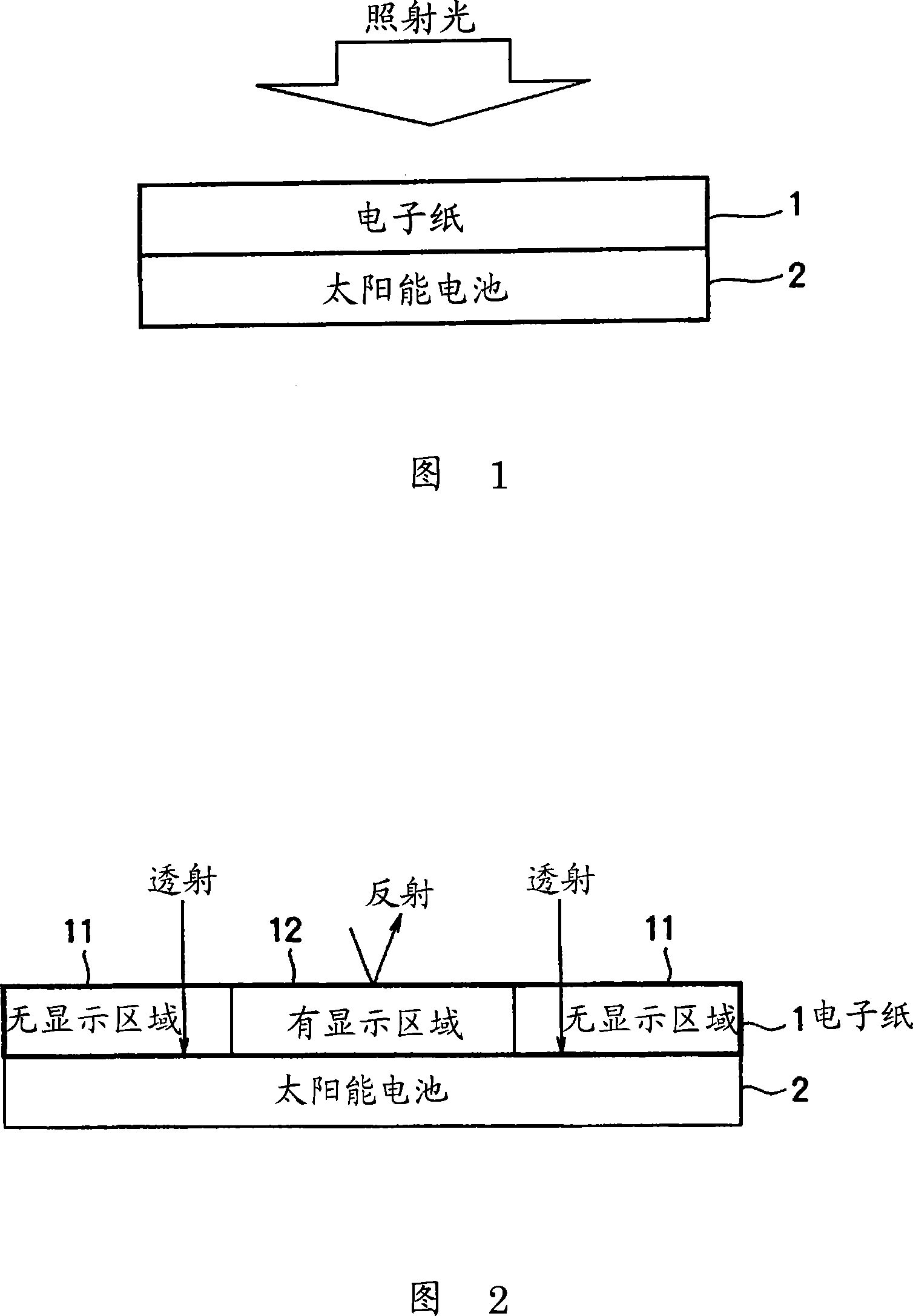
technical field [0001] The present invention relates to an electronic device, and more particularly, to an electronic device in which a solar cell is laminated on the back of a reflective display for displaying characters, graphics, etc. without changing the power generation efficiency of the solar cell. Background technique [0002] When mounting a solar cell on an electronic device, it is preferable to provide the solar cell on the outer surface of the electronic device so as to receive irradiated light with high efficiency. However, when mounting a display and a solar cell on a small electronic device, since the display needs to be provided on the outer side of the small electronic device, it is necessary to consider the arrangement of the display and the solar cell. [0003] For example, as shown in Fig. 1, a method has been proposed as a method of efficiently disposing displays and solar cells: an electronic paper 1 using a polymer network liquid crystal is used as a di...

Claims


Application Information

Patent Timeline
Patent Type & Authority Applications(China)
IPC IPC(8): G02F1/13G09F9/00G06K19/077H01L31/042
CPCY02E10/542G09G2300/0486Y02E10/52G02F2001/13478G02F2001/133567G02F2001/13324G09G3/36G09G2330/02G02F1/13718G02F1/13324G02F1/133567G02F1/13478
Inventor 石桥义人小高健太郎长井昭二久保野文夫
Owner SONY GRP CORP
Learn More