Filtering electrical sensor

A technology for filtering inductors and windings, applied in the field of inductors, can solve the problems of increased manufacturing cost and high difficulty of winding frames, and achieves the effects of improving the degree of freedom, saving wiring space, and improving the value of differential mode inductance.

Inactive Publication Date: 2008-02-13
DELTA ELECTRONICS INC
View PDF0 Cites 14 Cited by
  • Summary
  • Abstract
  • Description
  • Claims
  • Application Information

AI Technical Summary

Problems solved by technology

However, although the inductor 1 can eliminate electromagnetic interference, as far as the forming technology is concerned, it

Method used


Image

  • Filtering electrical sensor
  • Filtering electrical sensor
  • Filtering electrical sensor

Examples


Embodiment Construction

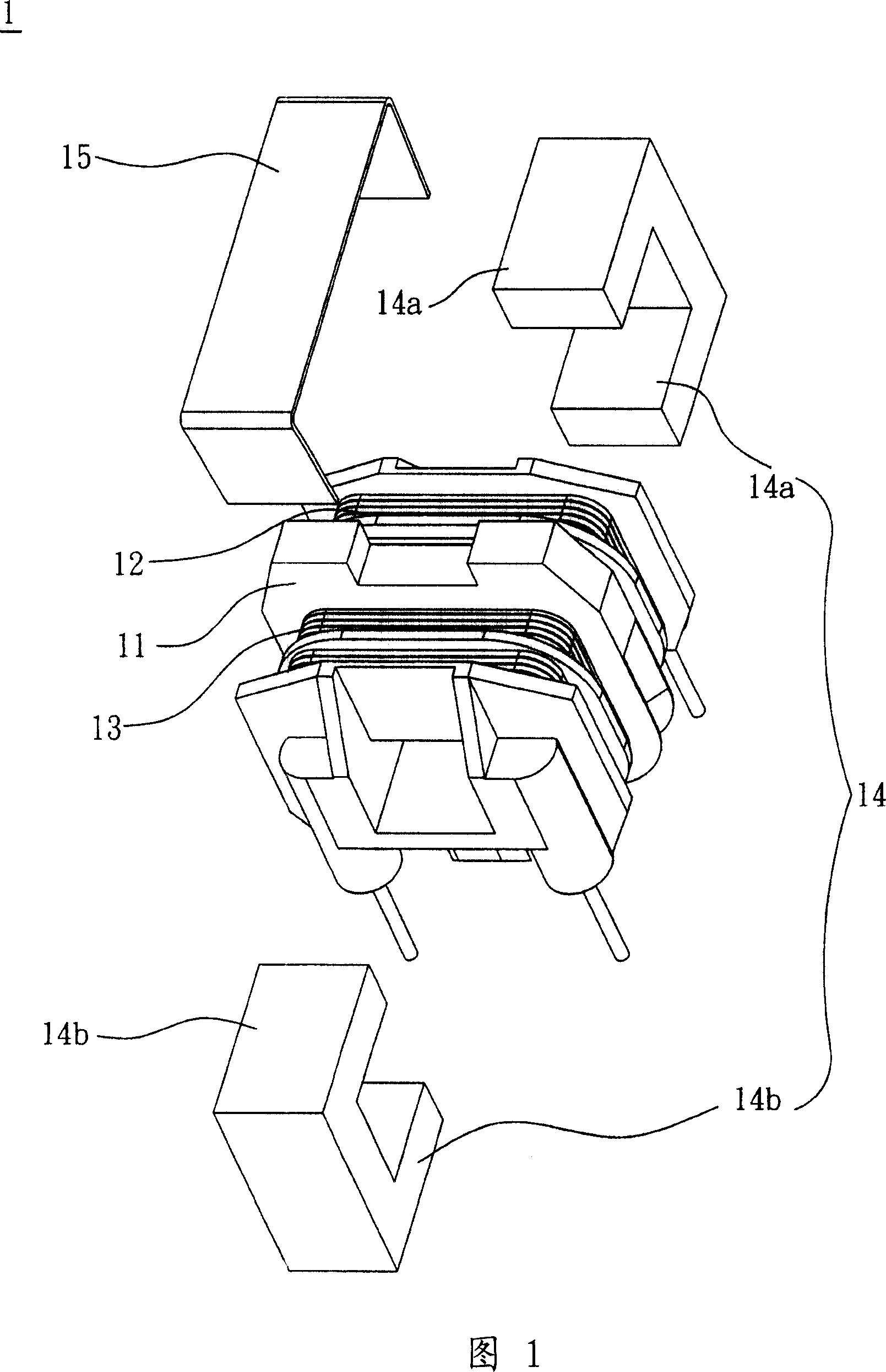
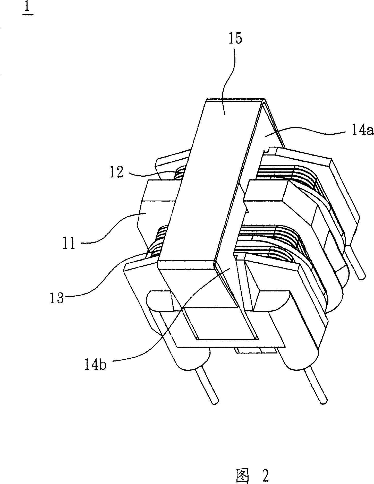
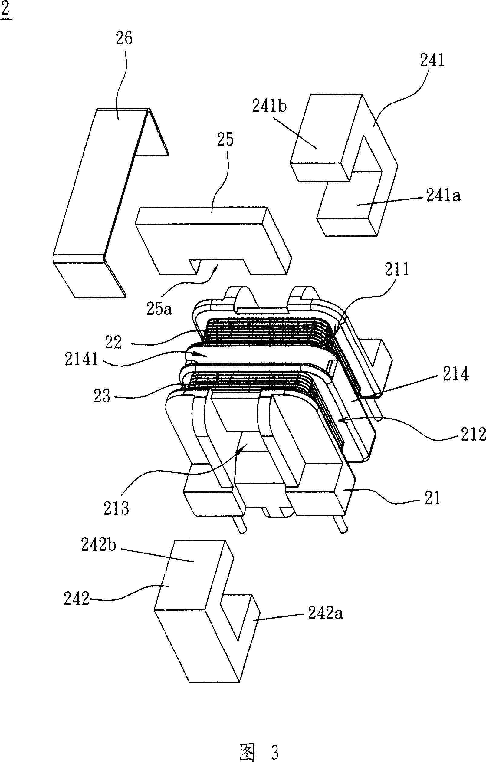
[0031] A filter inductor according to a preferred embodiment of the present invention will be described below with reference to related drawings, wherein the same elements will be described with the same reference symbols.

[0032] 3 and 4, according to a preferred embodiment of the present invention, a filter inductor 2 includes a bobbin 21, a first winding 22, a second winding 23, a core group 24 and a Magnetic conductor 25.

[0033] In this embodiment, the bobbin 21 has a first winding area 211 , a second winding area 212 and an isolation portion 214 . The isolation portion 214 is located between the first winding area 211 and the second winding area 212 and has a slot 2141 therein. The bobbin 21 also has a through hole 213 passing through the isolation portion 214 , the first winding area 211 and the second winding area 212 . The material of the bobbin frame 21 in this embodiment is not limited, but in practice, non-magnetic material is preferred, such as but not limited...


PUM


Abstract

The invention discloses a filtering inductor, which comprises a winding frame, a first winding, a second winding, an iron core group and a magnetic conductor. The first winding is wound outside the bobbin; the second winding is wound outside the bobbin, and the bobbin further has an insulating part to isolate the first winding and the second winding and has A slot is used for accommodating the magnetizer. A part of the iron core group passes through the winding frame, and the other part surrounds the winding frame, the first winding and the second winding outside, wherein the magnetic conductor and the iron core passing through the winding frame The group is contact-connected and separated from the iron core group outside the bobbin by an air gap.

Description

technical field [0001] The invention relates to an inductor, in particular to a filter inductor capable of simultaneously filtering out common-mode noise and differential-mode noise. Background technique [0002] Since the circuits of electronic devices often operate in high-frequency switching, such as power supplies or power converters, it is easy to generate Electro-Magnetic Interference (EMI), which in turn affects the operation of electronic devices; Interference can be divided into Radiant and Conductive. Radiated electromagnetic interference is transmitted directly through open space, and conducted electromagnetic interference is transmitted through wires. [0003] Conducted electromagnetic interference can be divided into common-mode noise and differential-mode noise according to the different conduction paths of the noise current. The differential-mode noise is when the current directions of two wires are opposite to each other. The opposite occurs; while common mo...

Claims


Application Information

Patent Timeline
IPC IPC(8): H01F17/04H01F37/00H01F27/24
Inventor 方荣展吴成丰
Owner DELTA ELECTRONICS INC
Why Eureka
Try Eureka