A testable multiprocessor system and a method for testing a processor system

A processor system, processor unit technology, applied in the direction of electrical digital data processing, instrumentation, measuring electrical, etc.

Inactive Publication Date: 2008-02-13
NXP BV
View PDF0 Cites 2 Cited by
  • Summary
  • Abstract
  • Description
  • Claims
  • Application Information

AI Technical Summary

Problems solved by technology

For example, in a multiprocessor with 200 modules, whenever a 16-bit test address register needs to be written or read, an additional 200 bypass bits need to be written or read, which is more than 10 times the overhead

Method used


Image

  • A testable multiprocessor system and a method for testing a processor system
  • A testable multiprocessor system and a method for testing a processor system
  • A testable multiprocessor system and a method for testing a processor system

Examples


Embodiment Construction

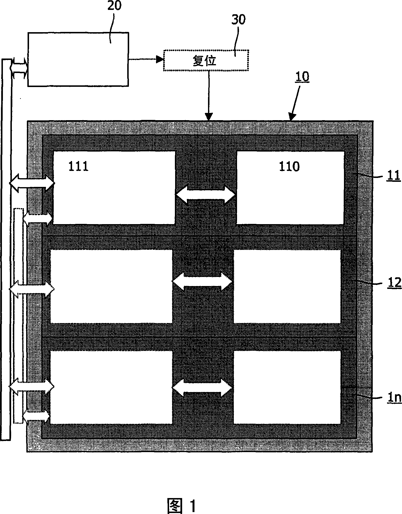
[0020] Fig. 1 schematically shows a testable processor system 10, 20 comprising a plurality of modules 11, 12, . . . , 1n. Each module includes a processor unit 110 and a debug controller 111 . The debug controller 111 is connected to a common TAP controller, such as the JTAG TAP controller 20 .

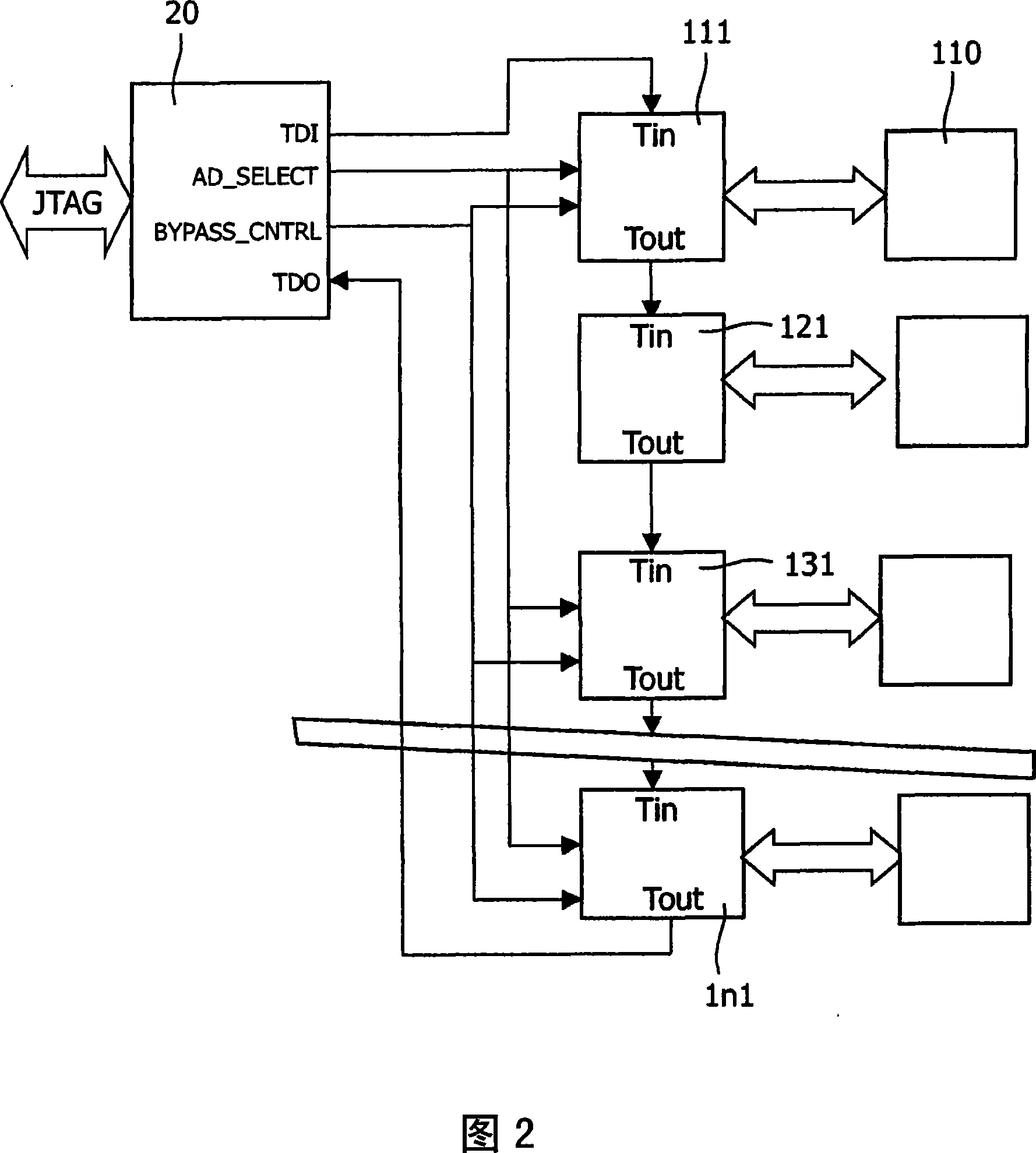
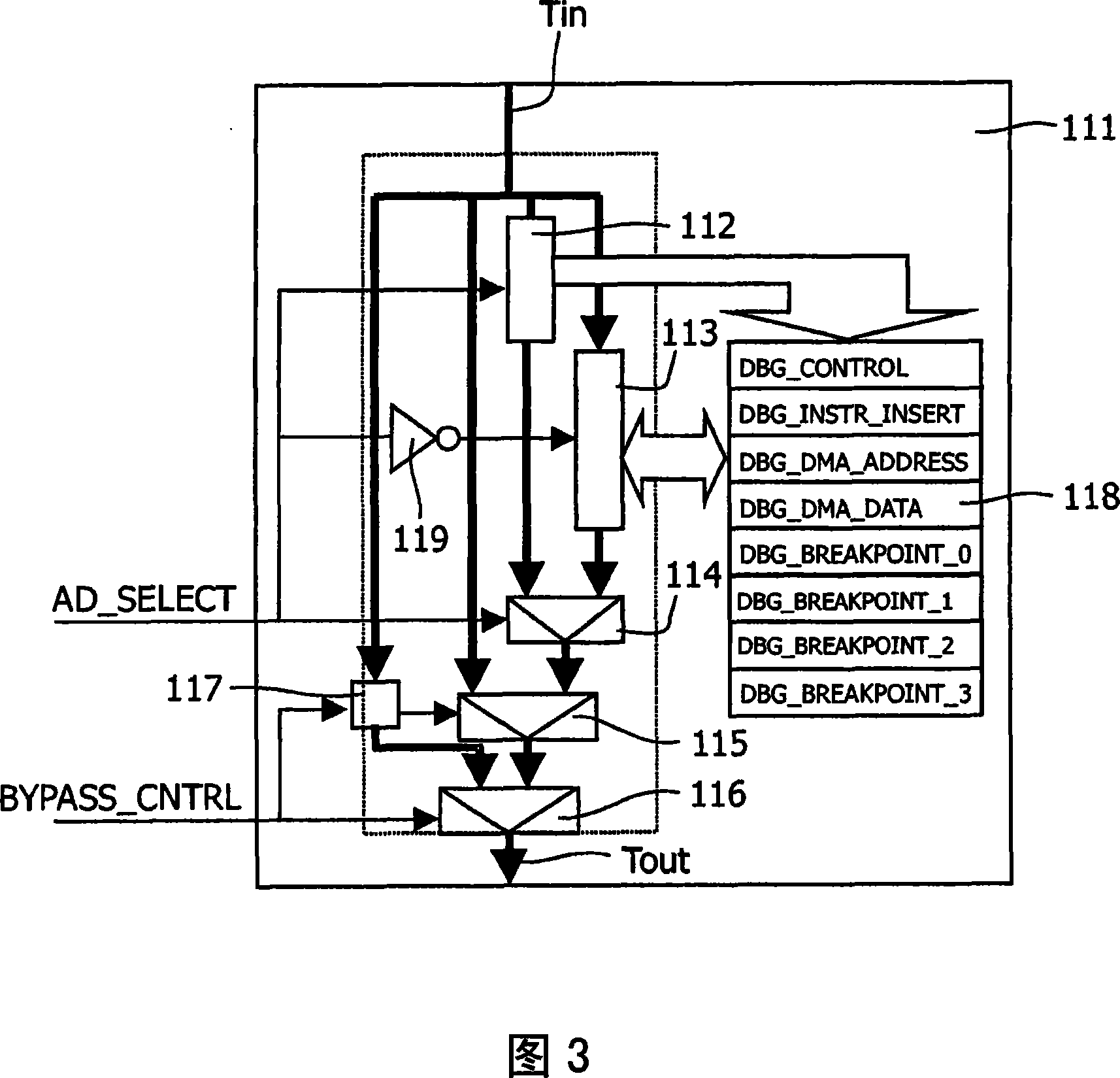
[0021] Figures 2 and 3 show a part of the system in more detail. The debug controllers 111, 121, 131, . . . , 1n1 have test data input terminals Tin and test data output terminals Tout and at least one test register (FIG. 3: 112, 113). In the illustrated embodiment, the debug controller has a test address register 112 and a test data register 113 . The test data input and output of the debug controller are arranged in a scan chain having an input for receiving test data data from the TAP controller, and an input for providing test data data TDO to the TAP controller. output. At least one debug controller 111 has a selection tool 115 that enables data in the scan chain to be moved...


PUM


Abstract

A testable processor system (10,20) comprises a plurality of modules (11,12,...In). Each module (11) comprises a processor unit (110) and a debug controller (111). The debug controllers are coupled to a common test access point controller (TAP- controller 20), and have a test data input (Tin), a test data output (Tout) and at least one test register (112, 113). The test data inputs and outputs of the debug controllers (111, 121, 131, ...,InI) are arranged in a scan chain having an input for receiving test input data (TDI) from the TAP-controller and an output for providing test output data (TDO) to the TAP-controller. At least one debug controller (111) has a selection facility (115) to select whether data in the scanchain is either shifted through the at least one test register (112) of that debug controller (111) or is immediately forwarded from the test data input (Tin) to the test data output (Tout) of that debug controller. The at least one debug controller has a bypass register (117) which controls the selection facility. The TAP-controller (20) provides a control signal (BYPASS CNTRL) which, when active, selects the bypass register as part of the scan chain.

Description

Background technique [0001] The growing number of more complex systems requires test tools that support system debugging. In order to support this requirement, JTAG (Joint Test Action Group, Joint Test Action Group) has developed a standard, which provides a generally accepted interface. Among them, it is proposed to test the system by connecting the system register groups to be tested in the scan chain. The registers may be registers that have been set up for normal operation, or may be specially created registers for testing. Move the input test data into the scan chain. After one or more cycles of operation, the output test data is shifted out of the scan chain and can be analyzed. This makes it possible to read and write large amounts of test data using only a small bandwidth connection. [0002] If each module in a multiprocessor system had such a scan chain, the bandwidth required in the multiprocessor system would still be large, which would diminish the advantages....

Claims


Application Information

Patent Timeline
Patent Type & Authority Applications(China)
IPC IPC(8): G06F11/267
CPCG01R31/31705G01R31/318558G06F11/2236
Inventor 马瑞那斯·范斯普朗特艾沃特·让·波尔
Owner NXP BV
Why Eureka
Try Eureka