Winding device for rewinding machine

A technology of coiling device and rewinding machine, which is applied in the direction of transportation and packaging, conveying filamentous materials, thin material processing, etc., can solve problems such as difficulties in automatic production, change of coil width, and limitation of relative rotation, etc., to reduce loading Dismantling steps, improving production efficiency, and simple and convenient operation

Active Publication Date: 2012-07-04
SUZHOU AOZHI INTELLIGENT EQUIP CO LTD
View PDF0 Cites 0 Cited by
  • Summary
  • Abstract
  • Description
  • Claims
  • Application Information

AI Technical Summary

Problems solved by technology

[0003] 1) The width of the produced coil needs to be changed;
[0004] 2) Although coils with the same width range are produced, due to slight changes in the outer diameter or ellipticity of the incoming copper tubes, the copper tubes cannot be arranged neatly within the original width range;
[0005] 3) There are gaps in the arrangement of the copper tubes on the bottom layer, which makes automatic production very difficult, so the operator must adjust the coil width after the bottom layer is arranged tightly to squeeze the copper tubes tightly;
[0008] And if will adjust volume width on the crimping device of existing rewinder, because bayonet 18 is installed on the second rotating disk 5 (thick dish) with screw, bayonet 18 blocks the chute on the core 6, limits The relative rotation between the bayonet 18 and the barrel core 6 is eliminated, so the bayonet 18 must be removed, and the thick disk 5 is manually rotated, and because the existing thick disk 5 has a bayonet 18 every 1 / 4 turn, Therefore, when adjusting the width of the roll, it can only be rotated by an integral multiple of 90 degrees
The minimum width to be adjusted is also related to the thread pitch on the first screw sleeve 12. The thread pitch cannot be too small, generally greater than 3mm. In this way, every 90 degrees of rotation, the width changes by about 0.75mm, and the coil cannot be adjusted continuously. Wide, unable to meet the requirements of fine-tuning, especially when coiling small-diameter tubes, it is difficult to accurately control the coil width

Method used


Image

  • Winding device for rewinding machine
  • Winding device for rewinding machine
  • Winding device for rewinding machine

Examples


Embodiment

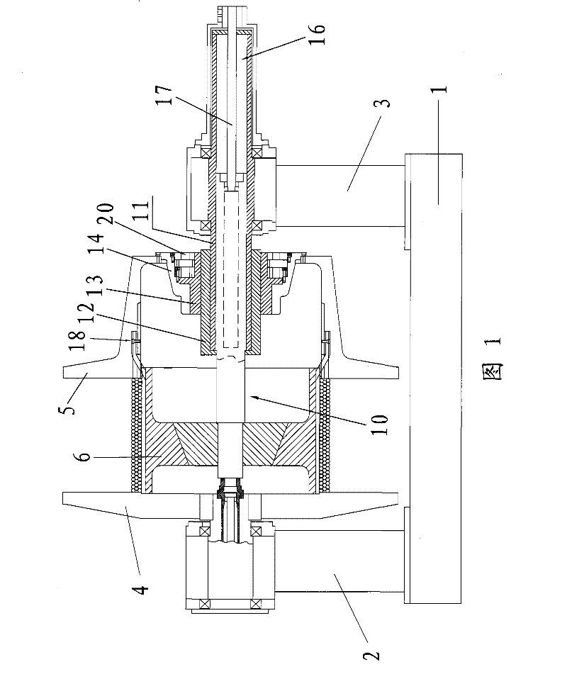
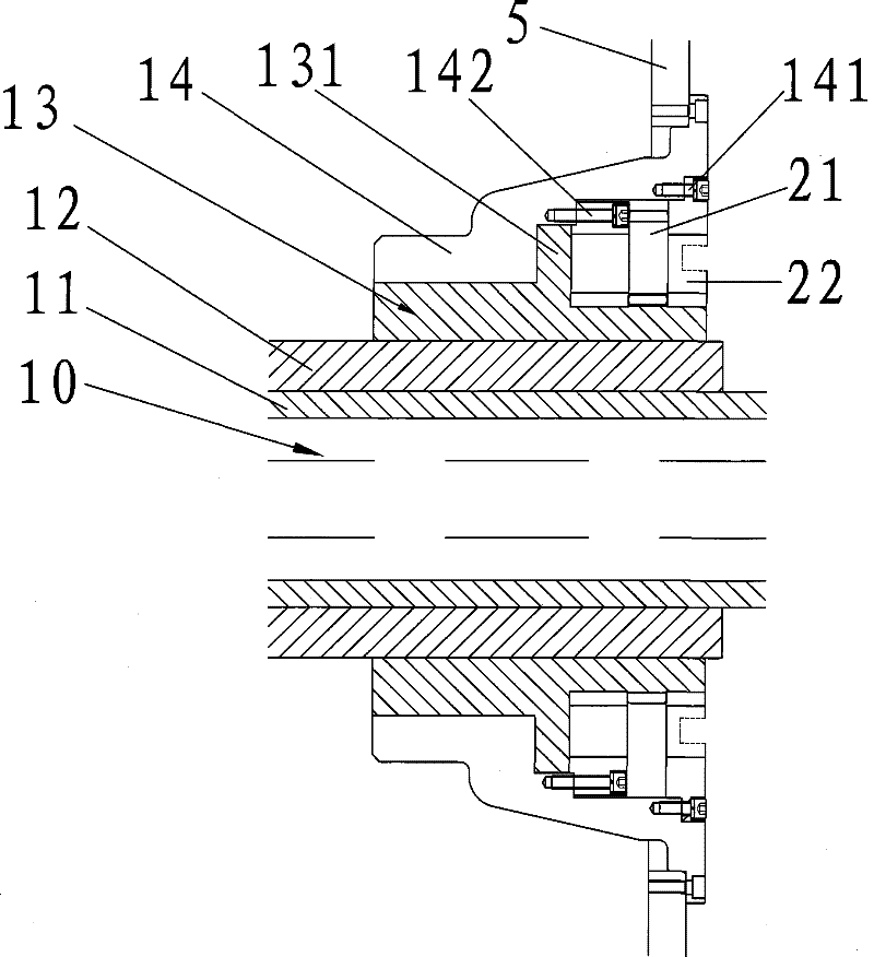
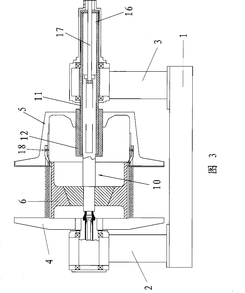
[0024] see figure 1 , a rewinding machine coiling device, which includes a bottom box 1 provided with a driving device, a first vertical arm 2 and a second vertical arm 3 fixedly arranged on the bottom box 1, rotatably arranged on the first vertical arm The first turntable 4 on the 2, the bushing 11 that is rotatably arranged on the second vertical arm 3, the sliding shaft 10 that can slide in the axial direction is housed in the bushing 11, and the sliding shaft 10 that is fixedly arranged on the sliding shaft 10 The core 6 that can be used to take up the copper pipe, the second turntable 5 that can be used to accommodate the core 6 and is detachably connected to the core 6, the sliding shaft 10 is fixed relative to the shaft sleeve 11, wherein the rewinding A roll width adjustment mechanism is also provided on the machine coiling device, and the roll width adjustment mechanism includes a first screw sleeve 12 which is slidably arranged on the outer surface of the shaft slee...


PUM


Abstract

The invention relates to a respooling machine coiling device, which comprises a first standing arm, a second standing arm, a first rotary plate which can be rotatablely positioned on the first standing arm, and a shaft sleeve which can be rotatablely positioned on the second standing arm, a slide shaft which can be moved along the axial direction is positioned in the shaft sleeve, a drum core which is fixedly positioned on the slide shaft and can coil the copper tube, and a second rotary plate which can contain the drum core and is connected with the drum core in a removable way. the slide shaft is rotated in respect to the shaft sleeve, wherein, the respooling machine coiling device is also provided with a coiling width adjusting mechanism, which comprises a first screw sleeve moveably positioned on the outside surface of the shaft sleeve, a second screw sleeve meshed with the first screw sleeve, a driving mechanism which is positioned on the second screw sleeve and can make the second screw sleeve rotated, and a connecting sleeve which is moveably positioned on the second screw sleeve and is fixedly connected with the second rotating plate. The second screw sleeve and the connecting sleeve are supported against with each other on the axial direction, and the second screw shaft can drive the connecting sleeve to axially move when the second screw sleeve is axially moving, thereby realizing the process of continuous adjusting coiling width.

Description

technical field [0001] The invention relates to a winding device for a rewinding machine, which is used for tightly and orderly winding copper pipes into coiled pipes, in particular to a winding device for a rewinding machine capable of fine-tuning the coil width. Background technique [0002] In the production process of the existing rewinding machine, there are often some situations that need to adjust the roll width, such as: [0003] 1) The width of the produced coil needs to be changed; [0004] 2) Although coils with the same width range are produced, due to slight changes in the outer diameter or ellipticity of the incoming copper tubes, the copper tubes cannot be arranged neatly within the original width range; [0005] 3) There are gaps in the arrangement of the copper tubes on the bottom layer, which makes automatic production very difficult, so the operator must adjust the coil width after the bottom layer is arranged tightly to squeeze the copper tubes tightly; ...

Claims


Application Information

Patent Timeline
Patent Type & Authority Patents(China)
IPC IPC(8): B65H54/02B65H54/40B65H54/70
Inventor 凌雪刚
Owner SUZHOU AOZHI INTELLIGENT EQUIP CO LTD
Why Eureka
Try Eureka