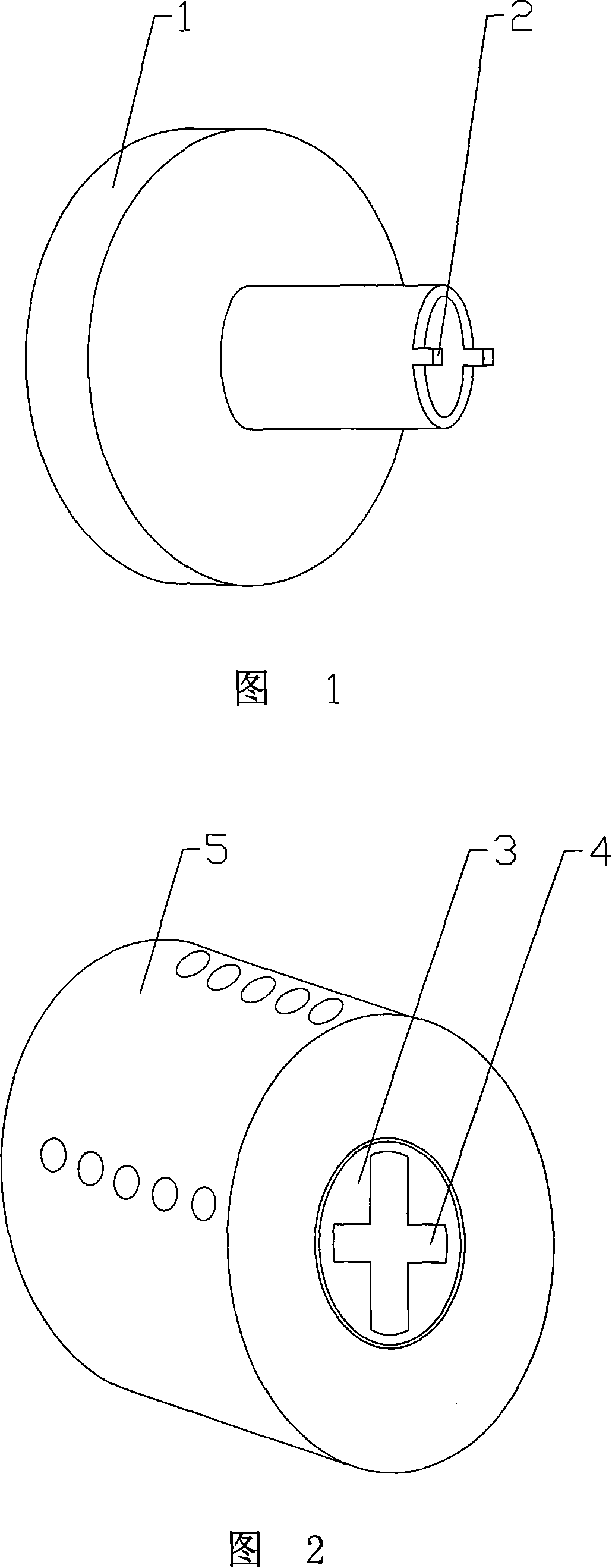
Locking head

A lock head and lock cylinder technology, applied in the field of locks, can solve problems such as unsatisfactory anti-technical performance, and achieve the effect of improving anti-technical opening performance

Inactive Publication Date: 2008-02-20
胡红远
View PDF0 Cites 0 Cited by
  • Summary
  • Abstract
  • Description
  • Claims
  • Application Information

AI Technical Summary

Problems solved by technology

Therefore, the performance of the existing locking anti-technical opening is not ideal

Method used


Image

  • Locking head
  • Locking head

Examples


Embodiment Construction

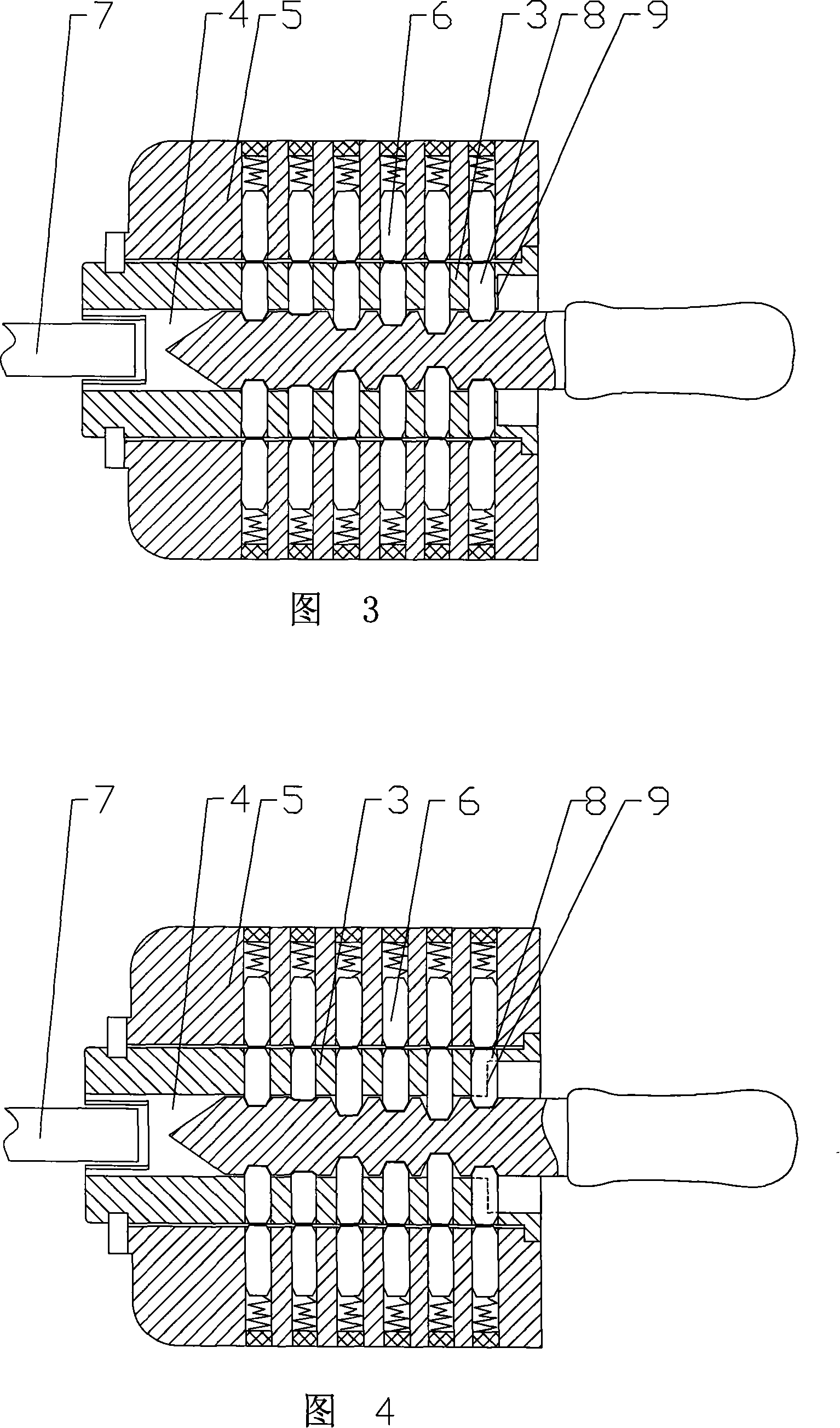
[0016] As shown in Figure 3: the lock head of this embodiment includes: a lock head shell 5 and a lock core 3, a key hole 4 is provided in the lock core, at least two columns of pins 6 arranged oppositely are arranged in the lock head shell and the lock core, The afterbody of the lock cylinder is connected with a transmission member 7, and the key hole is provided with a blocking structure that prevents the plug of the unlocking tool from being inserted and twisted. The keyhole is a slotted hole, and the blocking structure is that the front side of the frontmost marble 8 is less than 0.3mm from the front side of the lock cylinder front end 9. In this embodiment, the outer shape of the lock housing can be designed according to requirements.

[0017] When the distance between the front side of the most front pin and the front face of the lock core is less than 0.3mm, it is difficult for the thief to apply torque to the lock core through the key hole; A step will be formed and d...


PUM


Abstract

The invention relates to a tapered ned which comprises a tapered ned case and a plug. The plug is provided with a keyhole, at least two rows of pin tumblers which are arranged in the opposite way are arranged in the tapered ned case and the plug, the tail of the plug is connected with a driving piece. The keyhole is provided with a barrier structure which can prevent the unlocking tool from inserting and can prevent the torsion. As the key hole is provided with the barrier structure which can prevent the unlocking tool from inserting and can prevent the torsion, the thief cannot apply torsion to the plug through the keyhole; the groove for the pin tumbler in the plug does not form a step with the groove for the pin tumbler in the tapered ned, and thus the resistance to technical opening of the tapered net is considerably improved.

Description

Technical field: [0001] The invention relates to the field of locks, in particular to a lock head. Background technique: [0002] Existing locks are generally equipped with multiple groups of conical or cylindrical pins in the lock shell and the lock cylinder. With the lock of this structure, thieves can easily open the lock through the elastic hook. The general working principle of technical opening is as follows: Since the pins in the lock cylinder need to be able to move under pressure during normal opening, the width of the pin grooves should be larger than the diameter of the pins. As shown in Figure 1 and Figure 2, in the technical opening process, first insert the plug 2 of the unlocking tool 1 into the key hole 4 in the lock cylinder 3, and press the unlocking tool so that the lock cylinder bears a certain torque; under the action of the torque , the marble groove in the lock core 3 and the marble groove in the lock end shell 5 just form a step. At this time, the t...

Claims


Application Information

Patent Timeline
Patent Type & Authority Applications(China)
IPC IPC(8): E05B27/08
Inventor 胡红远
Owner 胡红远
Why Eureka
Try Eureka