Laser-driven open circuit detection circuit

A technology of laser driving and open circuit detection, which is applied in the field of detection circuit, can solve the problems of energy consumption, consumption of voltage margin, reduction of laser LD modulation current, etc., and achieves the effect of simple structure and easy realization

Pending Publication Date: 2022-05-10
XIAMEN UX HIGH SPEED IC
View PDF0 Cites 0 Cited by
  • Summary
  • Abstract
  • Description
  • Claims
  • Application Information

AI Technical Summary

Problems solved by technology

[0005] 1. Connecting a resistor in series with the output terminal of the laser LD will reduce the modulation current of the laser LD
[0006] 2. Connecting a resistor in series with the laser LD at the output end will consume a certain voltage margin and generate unnecessary energy consumption at the same time
[0007] 3. A resistor connected in series with the laser LD at the output end will affect the performance of the drive current (rise and fall time, amplitude, etc.)
[0008] 4. The presence of parasitic capacitance at the input of the DIFF_AMP amplifier will also affect the bandwidth of the drive circuit, which in turn affects the rise and fall time of the drive current, etc.

Method used


Image

  • Laser-driven open circuit detection circuit
  • Laser-driven open circuit detection circuit
  • Laser-driven open circuit detection circuit

Examples


Embodiment 1

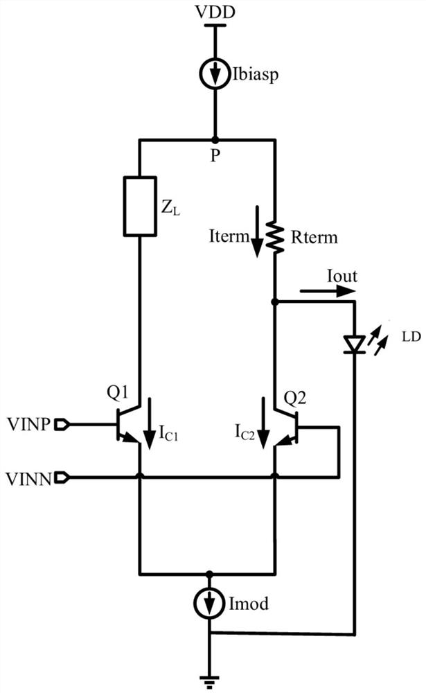
[0034] Example 1, please refer to figure 2 with image 3 :

[0035] Laser drive open circuit detection circuit, including laser drive circuit, laser LD, please refer to figure 2 , the laser drive circuit includes a first triode and a second triode capable of forming a differential circuit, the control terminals of the first triode and the second triode are respectively connected to the first input terminal and the second input terminal , one end of the first triode is connected to the load Z L connected to the output end of the first constant current source Ibiasp, the other end of the first triode is connected to the input end of the second constant current source Imod, and one end of the second triode is connected to the first The output end of a constant current source Ibiasp, the other end of the second triode is connected to the input end of the second constant current source Imod, the output end of the second constant current source Imod is grounded, and the laser L...

Embodiment 2

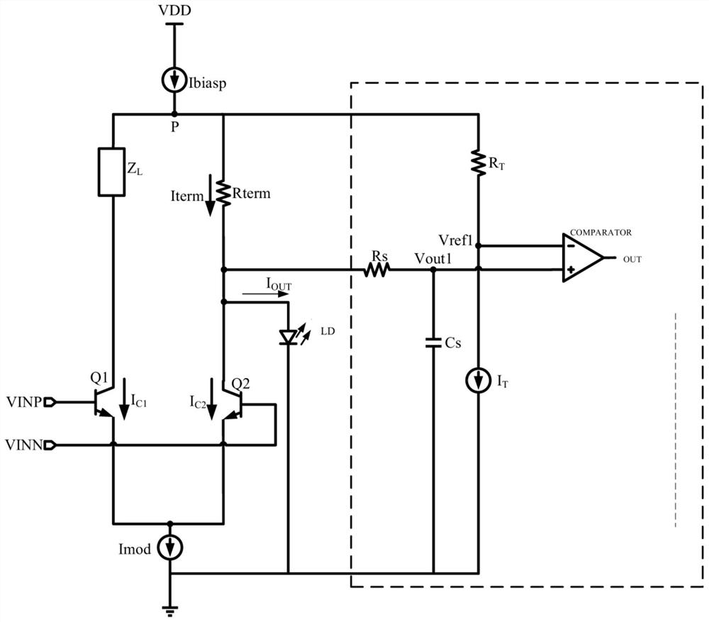
[0060] Example 2, please refer to Figure 4 :

[0061] The laser drive open circuit detection circuit includes a laser drive circuit and a laser LD. The laser drive circuit includes a main circuit and two branches branched from the main circuit and connected in parallel. A common end of the two branches is connected to the main circuit. The other common end is grounded, the first constant current source Ibiasp and the resistor Rterm are connected in series on the trunk, one branch of which is connected in series with the second constant current source Imod, and the other branch is connected in series with the laser LD, through the first constant current source Ibiasp and the second constant current source Imod drive the laser LD to work.

[0062] According to the same detection principle as in Embodiment 1, an open circuit detection circuit is designed for the laser drive circuit of Embodiment 2, and the open circuit detection circuit also includes a resistor R T , resistanc...


PUM


Abstract

The invention discloses a laser driving open circuit detection circuit which comprises a laser driving circuit, a laser device LD, a resistor RT, a resistor Rs, a third constant current source IT and a comparer COMPARATOR, the resistor RT and the third constant current source IT are connected in series, the two ends of the resistor RT and the third constant current source IT are connected between the positive end of a resistor Rterm and the ground, one end of the resistor RT is connected with the positive end of the resistor Rterm, and the other end of the resistor Rs is connected with the positive end of the resistor Rterm. One end of the resistor RT is connected with the negative end of the resistor Rterm, the other end of the resistor RT is connected with the third constant current source IT and one input end of the comparator COMPARATOR, one end of the resistor Rs is connected with the negative end of the resistor Rterm, the other end of the resistor Rs is connected with the other input end of the comparator COMPARATOR, the voltage of the other end of the resistor RT is the voltage Vref1, the voltage of the other end of the resistor Rs is the voltage Vout1, and by comparing the voltage Vref1 with the voltage Vout1, the voltage of the other end of the resistor Rs is calculated. And judging whether the laser driving circuit is open-circuited with the laser LD or not. The device has the advantages that laser driving open circuit detection is realized easily, power failure or external detection tools are not needed, and normal work of the laser driving circuit and the laser is not affected.

Description

technical field [0001] The invention relates to a detection circuit, in particular to a laser-driven open circuit detection circuit. Background technique [0002] In the production process of the laser driver module (especially in the packaging and bonding process of the laser LD and the driver chip) or in the use stage of the laser driver module (due to external force factors or others), there will be a disconnection between the driver chip and the laser LD. The phenomenon of turning on, so that the driving current cannot flow into the laser LD normally, and the laser LD does not emit light. However, powering off the driver module and using a third-party testing tool can detect the open circuit problem between the driver chip and the laser LD, but this method is obviously time-consuming and resource-intensive. In order to reduce the detection time and cost of open-circuit bonding, it is necessary to design a detection circuit inside the driver chip that can automatically d...

Claims


Application Information

Patent Timeline
Patent Type & Authority Applications(China)
IPC IPC(8): G01R31/54
CPCG01R31/54
Inventor 郑永华李发明林永辉林文礼杨龙东陈哲葛军华
Owner XIAMEN UX HIGH SPEED IC
Why Eureka
Try Eureka