A wide-range wiper structure controlled by a single motor

A wiper structure and a large-scale technology, applied in the direction of cleaning methods using tools, cleaning methods and utensils, chemical instruments and methods, etc., can solve the problem that the available space of the wiper driving device is small, the range of scraping and cleaning is limited, and the design cannot be met Need and other problems, to achieve the effect of large scraping range, compact structure and small space occupation

Active Publication Date: 2022-06-17
成都辰天信息科技有限公司
View PDF19 Cites 0 Cited by
  • Summary
  • Abstract
  • Description
  • Claims
  • Application Information

AI Technical Summary

Problems solved by technology

Since there are many functional modules inside the radar itself, most of the space needs to be occupied, so the available space for the wiper driving device is very small. Therefore, the wiper coverage of the existing FOD radar is small, and generally only in the normal Use the wiper on some small areas of the protective glass of the optical lens, and the cleaning range is very limited. When the optical lens rotates at an angle, some protective glass in front of the lens may not be cleaned, which is easy In addition, if the radar design also includes other protective glass with cleaning requirements such as lens fill light, the existing wiper cleaning range cannot meet the design requirements.

Method used


Image

  • A wide-range wiper structure controlled by a single motor
  • A wide-range wiper structure controlled by a single motor
  • A wide-range wiper structure controlled by a single motor

Examples


Embodiment Construction

[0027] In order to make the technical problems, technical solutions and beneficial effects solved by the invention clearer, the invention will be further described below with reference to the accompanying drawings and embodiments. The present invention may be implemented in many different forms and is not limited to the embodiments described herein.

[0028] Unless otherwise defined, technical and scientific terms used herein have the same meaning as commonly understood by one of ordinary skill in the technical field to which this invention belongs. The terms used herein in the description of the present invention are for the purpose of describing specific embodiments only, and are not intended to limit the present invention.

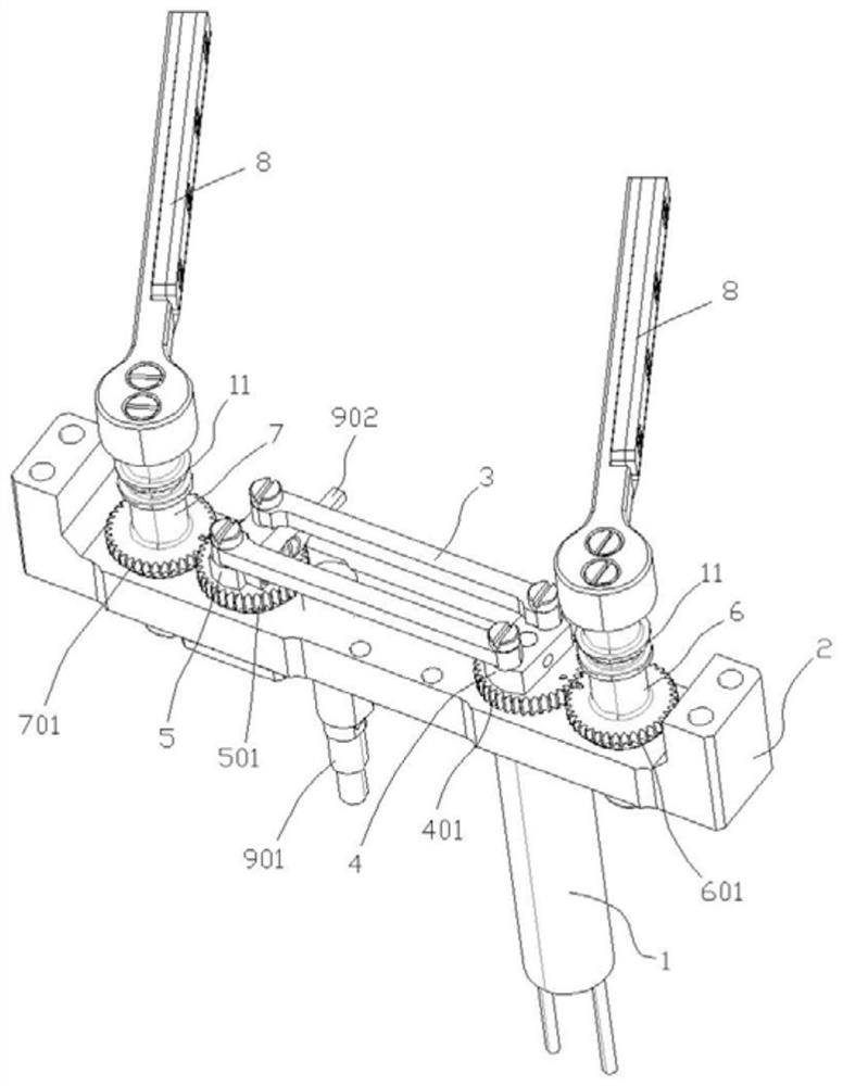
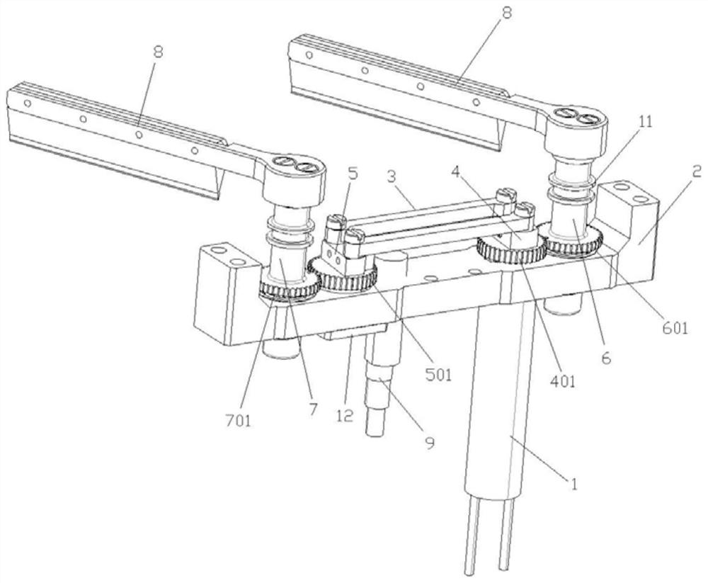
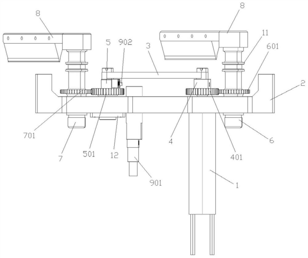
[0029] The large-scale wiper structure controlled by a single motor provided by this embodiment is as follows: Figure 1-8 As shown, it includes a motor 1, a mounting seat 2 and a connecting rod 3. The mounting seat 2 is provided with a driving gear sh...


PUM


Abstract

The invention specifically discloses a large-scale wiper structure controlled by a single motor, including a motor, a mounting seat and a connecting rod. The mounting seat is provided with a driving gear shaft and a driven gear shaft. The other end of the rod is connected to the driven gear shaft, the motor is connected to the driving gear shaft, and the first pinion shaft and the second pinion shaft are also arranged on the mounting base, and the driving gear shaft and the driven gear shaft are arranged on the first pinion shaft and the second pinion shaft. Between the gear shafts, the driving gear shaft and the first gear shaft are engaged for transmission, and the driven gear shaft is engaged for transmission with the second gear shaft. Both the first gear shaft and the second gear shaft are connected with a wiper assembly. The wiper structure is used It is used to scrape and clean the optical lens and fill light lens on the radar to ensure that the lens can be rotated and shot clearly in various weathers and environments; the structure is compact, the installation is convenient, the space is small, the overall structure is independent, and it can be used independently The installation will not affect the working performance of other modules on the radar, and the scratching range is larger.

Description

technical field [0001] The invention relates to the technical field of wipers, in particular to a large-scale wiper structure controlled by a single motor. Background technique [0002] At present, all FOD radars require a compact and short overall structure. The purpose is to minimize the volume of the radars arranged on both sides of the runway and avoid the pressure on the pilots due to the excessive volume. Since there are many functional modules inside the radar, it needs to occupy most of the space, so the available space for the wiper drive device is very small. Therefore, the existing FOD radar has a small wiper coverage area, generally only in the positive direction. Use wipers on some small areas of the protective glass of the optical lens. The cleaning range is very limited. When the optical lens is rotated with an angle, there may be some protective glass in front of the lens that will not be cleaned. This situation is very easy It affects the monitoring effect ...

Claims


Application Information

Patent Timeline
Patent Type & Authority Patents(China)
IPC IPC(8): B08B1/02B08B1/00B08B13/00
CPCB08B1/02B08B1/005B08B13/00
Inventor 赵智忠冯静
Owner 成都辰天信息科技有限公司
Why Eureka
Try Eureka