Combined cooling structure for turbine blade middle-part round-corner transition impact aerating film

A technology of rounded transition and turbine blades, which is applied in the directions of blade support elements, engine elements, machines/engines, etc., can solve the problems of insufficient blade cooling and increased disturbance, and achieve improved heat exchange, reduced flow resistance, and improved cooling. effect of effect

Inactive Publication Date: 2008-02-20
BEIHANG UNIV
View PDF0 Cites 6 Cited by
  • Summary
  • Abstract
  • Description
  • Claims
  • Application Information

AI Technical Summary

Problems solved by technology

Most of the conventional turbine blades currently designed are arranged with ribs of various shapes inside the blades to increase the internal disturbance and improve the heat transfer effect, and some air film holes with small diameters are often arranged on the outer surface of the blades. , forming a full gas film coverage, the cooling effect of the turbine blade designed in this way is generally around 0.5, with the increase of the gas temperature in front of the turbine, such a cooling effect is obviously not enough for blade cooling, so it has a relatively high The invention of the turbo cooling structure with high cooling effect is very important and urgent

Method used


Image

  • Combined cooling structure for turbine blade middle-part round-corner transition impact aerating film
  • Combined cooling structure for turbine blade middle-part round-corner transition impact aerating film

Examples


Embodiment Construction

[0013] The present invention will be further described in detail below in conjunction with the accompanying drawings.

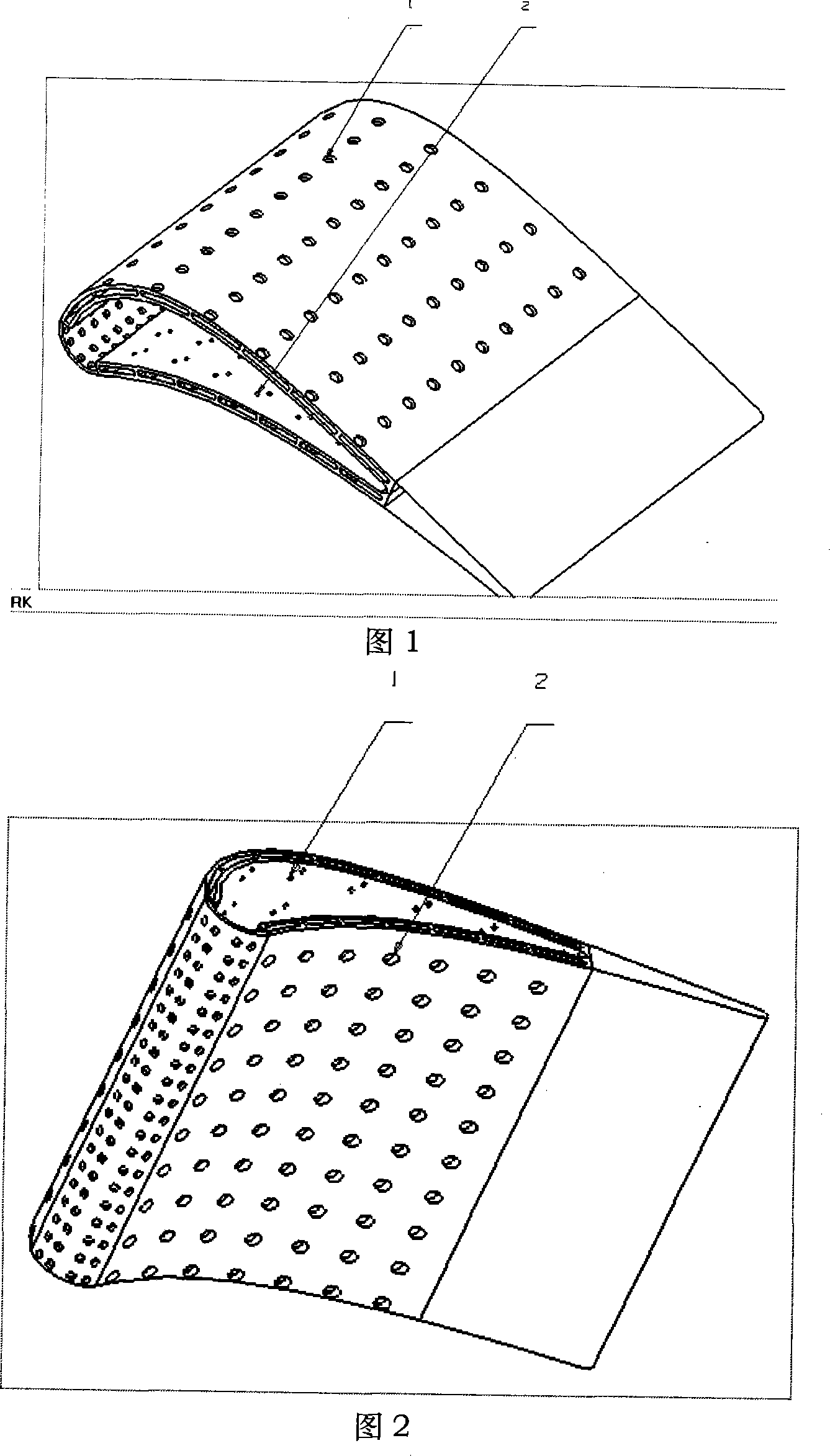
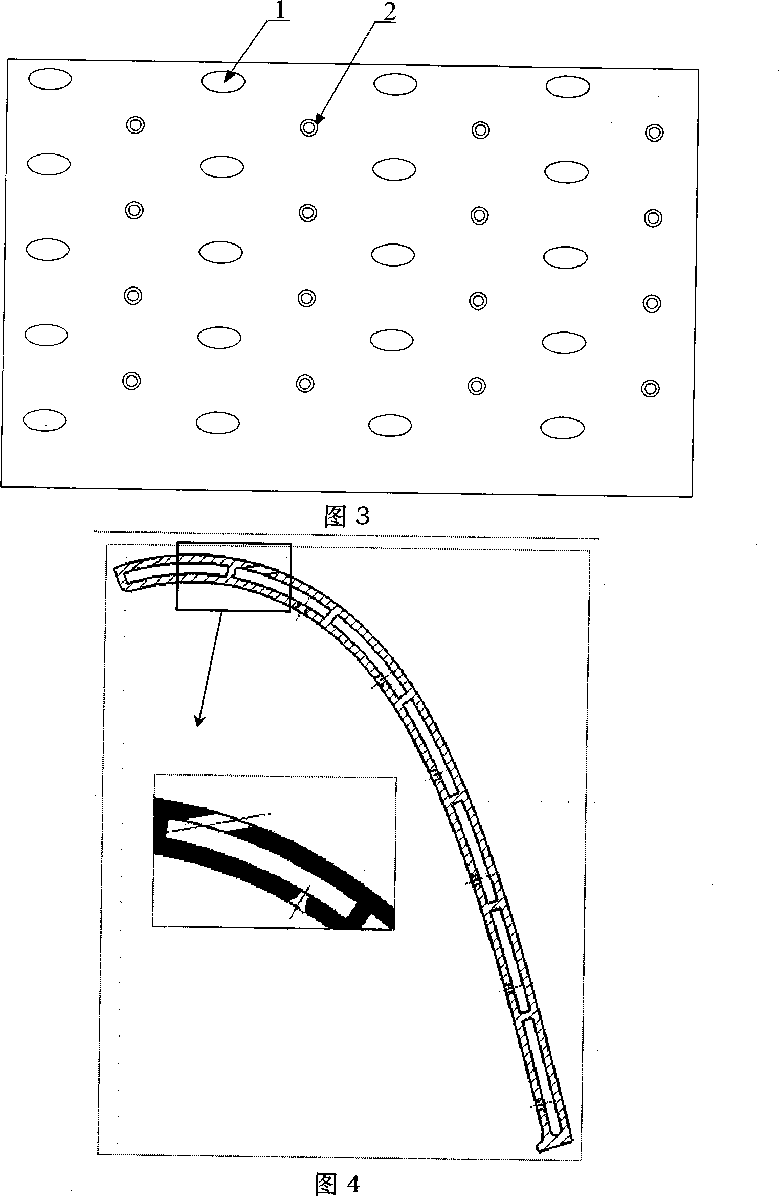
[0014] As shown in Fig. 1, the present invention is a combined cooling structure applied to the fillet transition impingement air-entraining film in the middle of the turbine blade of an aero-engine. Air film holes, the number of each exhaust film hole in the span direction is 10 to 20, and the impact holes with the same number as the air film holes are arranged in the downstream area of ​​the air film holes inside the blade, and the entrance of the impact holes adopts a rounded transition , the radius of the fillet is 0.3-0.6mm, there is no fillet at the exit of the impact hole, and the vertical incidence is maintained. Between the membrane holes, impact holes and air film holes are arranged alternately. The diameter of the air film holes is 2 to 2.5 times the diameter of the exit of the impact holes, and the spanwise spacing of the air film holes is 4 to 5 ...


PUM


Abstract

The invention discloses a round corner transition impact and air film combination cooling structure used at the middle of the turbine blades of an aeroengine. The cooling structure is that: air film holes with the diameter of 1.0 mm-1.5 mm are arranged on the outer surface of the blade, the amount of the air film holes at each extension direction is 10-20, impact holes are arranged inside the blades in the downstream area of the air film holes, the amount of the impact holes equals to that of the air film holes, the inlets of the impact holes adopt round corner transition and the diameter of the round corner is 0.3-0.6 mm. The impact holes with round corner transition are used for reducing the flow resistance and at the same time, guarantee that the outlet speed of the impact holes is not decreased. A highly cooling area with the large area is formed at the inner surface of the blades; at the same time, the highly cooling area is combined with an air film protection area formed by the air film holes which are sparsely arranged outside the blades to jointly meet the blade-cooling requirement. The results of the three-dimensional numerical simulation indicate that the cooling effect of the blades can reach 0.7 at least; at the same time, the pneumatic loss can be reduced distinctly and the flow resistance is distinctly lower than the ordinary turbine blades owing to the characteristic of the cooling structure.

Description

technical field [0001] The invention relates to a combined cooling structure with fillet transition impinging an air-entrained film. The cooling structure is mainly used in the middle of an aeroengine turbine blade and can produce a cooling effect of more than 0.7 to meet the cooling requirements of the aeroengine turbine blade. Background technique [0002] The most important performance index of an engine is the thrust-to-weight ratio. As people's performance requirements for the engine continue to increase, so do the requirements for the thrust-to-weight ratio. The most effective means to improve the thrust-to-weight ratio of the engine is to increase the gas temperature in front of the turbine. The pre-researched thrust-to-weight ratio 10 aero-engine before the turbine temperature is about 1850K ~ 1950K. However, the various materials currently used can only maintain their high strength indicators at about 1300 °C without cooling. Whether the turbine rotor can work saf...

Claims


Application Information

Patent Timeline
Patent Type & Authority Applications(China)
IPC IPC(8): F01D5/18
Inventor 孙纪宁罗翔丁水汀陶智徐国强王开
Owner BEIHANG UNIV
Why Eureka
Try Eureka