X-ray ct apparatus

一种X射线、设备的技术,应用在X射线CT设备领域,能够解决噪声量增加、层析图像质量下降等问题

Inactive Publication Date: 2008-02-20
HITACHI LTD
View PDF2 Cites 13 Cited by
  • Summary
  • Abstract
  • Description
  • Claims
  • Application Information

AI Technical Summary

Problems solved by technology

That is, even if the existing technology has been adopted, the problem of the degradation of tomographic image quality in the part where the subject has many bones due to the increase in the amount of noise due to insufficient transmitted X-ray intensity remains unsolved

Method used


Image

  • X-ray ct apparatus
  • X-ray ct apparatus
  • X-ray ct apparatus

Examples


Embodiment Construction

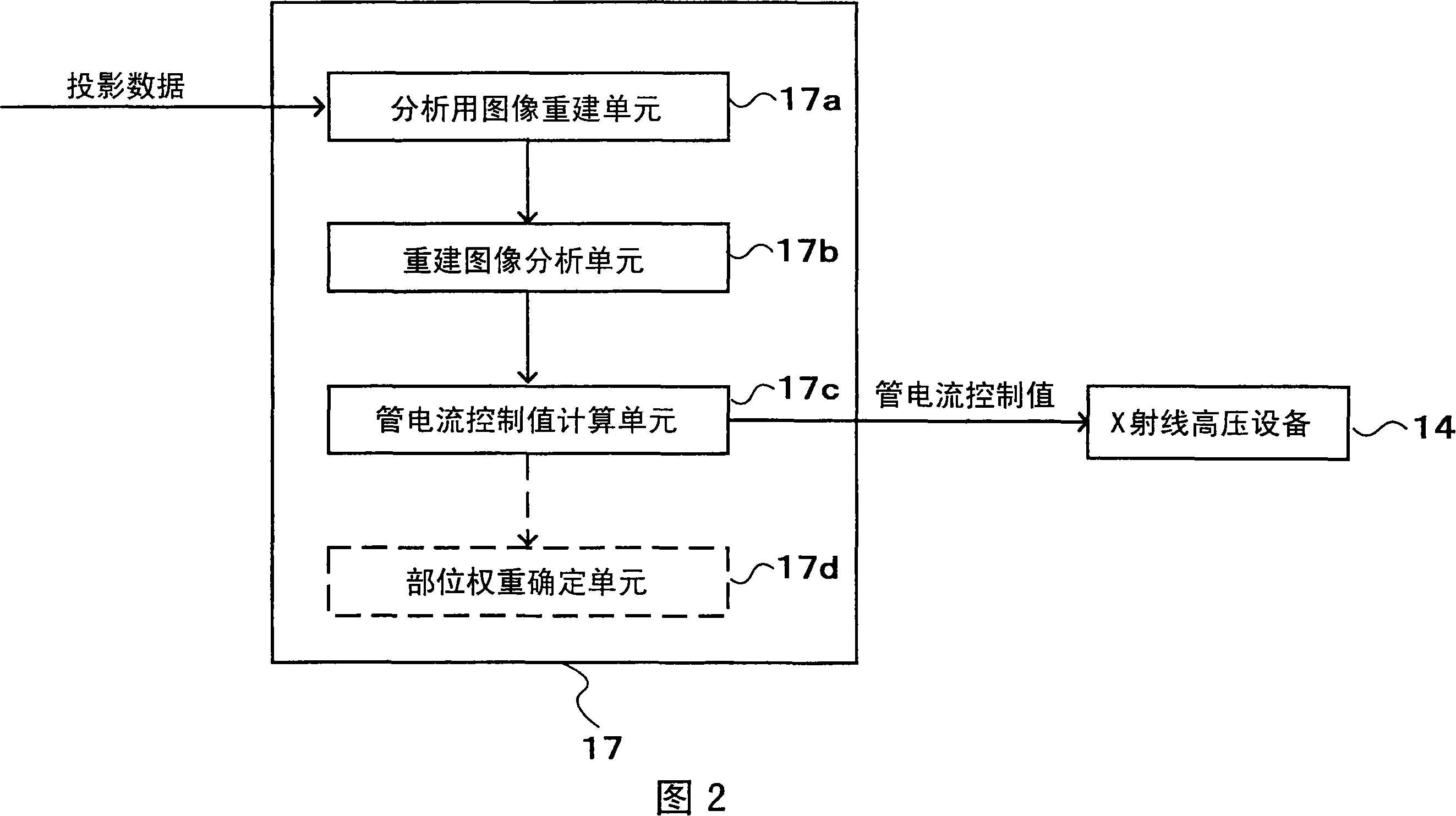
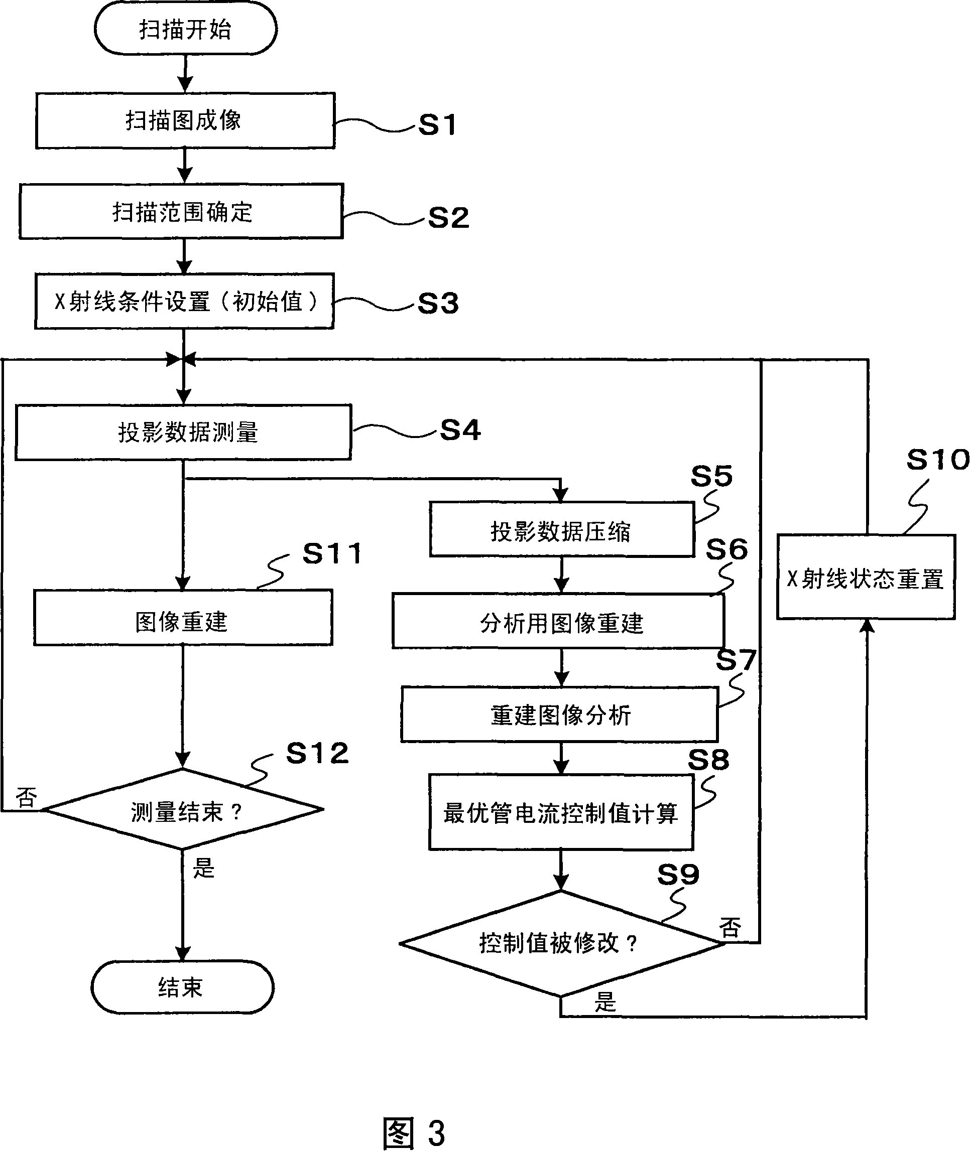
[0022] Hereinafter, embodiments of the X-ray CT apparatus of the present invention will be explained with reference to the drawings. The X-ray CT apparatus 1 according to the present embodiment measures the projection data of the subject while controlling the X-ray tube current according to the X-ray tube position (θ, z). Furthermore, among all the drawings for explaining the embodiments of the present invention, the drawings having the same function are assigned the same reference numerals, and its repeated explanation will be omitted.

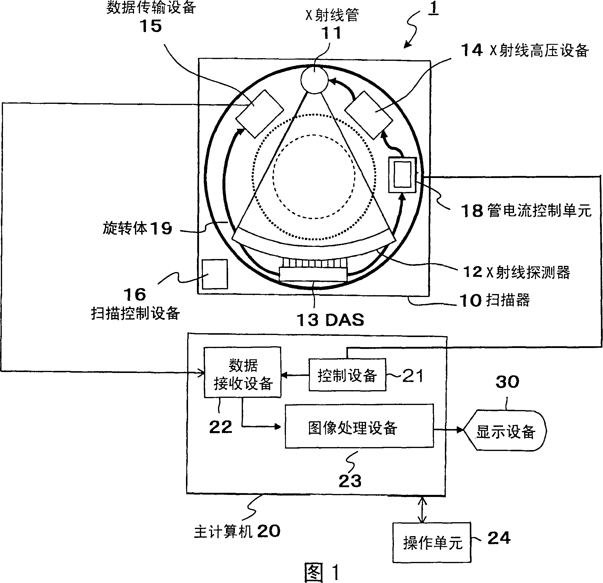
[0023] FIG. 1 shows the composition of the X-ray CT apparatus according to the present embodiment. This X-ray CT apparatus 1 is composed of a scanner 10 , a host computer 20 connected to the scanner 10 , an operation unit 24 connected to the host computer 10 , and a display unit 30 .

[0024] First, the scanner 10 constituent units are explained.

[0025] The X-ray tube 11 irradiates X-rays to the subject. The X-ray detector 12 is placed o...


PUM


Abstract

An X-ray CT device, comprising: an X-ray source for irradiating X-rays to a subject; an X-ray detector placed opposite to the X-ray source so that the subject is located between the X-ray detector and the X-ray source , and is used to detect X-rays transmitted through the subject as projection data; the rotating device rotates the X-ray source and the X-ray detector; the control device rotates the X-ray tube and the X-ray detector from the rotating device The obtained projection data is collected in multiple angle directions, the collected projection data is reconstructed and calculated to generate a tomogram of the subject, and the X-ray source and the rotating device are controlled; and a display device is used to display the generated tomogram. The X-ray CT apparatus further includes: a projection data analysis device for reconstructing a tomogram of an imaging site for analysis of the subject from the projection data, and generating a control curve by re-projecting the reconstructed tomographic image; a tube current control device, The value of the current fed into the X-ray tube is controlled according to the generated control curve.

Description

technical field [0001] The present invention relates to an improvement of X-ray CT equipment, which makes it possible to control the X-ray source current (hereinafter referred to as X-ray tube current) fed into the X-ray source (hereinafter referred to as X-ray tube) according to the The position in the direction of the body axis of the subject determines the X-ray irradiation density in the imaging site of the subject. [0002] This application claims Paris Convention priority based on Japanese Patent Application No. 2005-051497 under the Japanese Patent Law, and enjoys the benefit of Japanese Patent Application No. 2005-051497 by reference. Background technique [0003] The image quality obtained by X-ray CT equipment is determined by factors such as spatial resolution and the noise contained in the image. Among the above factors, image noise mainly depends on the X-ray transmission intensity. The X-ray transmission intensity is determined by the X-ray irradiation intens...

Claims


Application Information

Patent Timeline
Patent Type & Authority Applications(China)
IPC IPC(8): A61B6/03
CPCA61B6/032A61B6/542
Inventor 宫崎靖广川浩一入江敏之
Owner HITACHI LTD
Why Eureka
Try Eureka