
Ring-shaped sliding rail air operated machine

A circular-shaped, wind-driven technology, applied to wind engines, motors, and wind engines at right angles to the wind direction, etc., can solve the problems of heavy weight, difficult manufacture, and high price of wind blades

Inactive Publication Date: 2008-02-27
葛志仁
View PDF0 Cites 8 Cited by
  • Summary
  • Abstract
  • Description
  • Claims
  • Application Information

AI Technical Summary

Problems solved by technology

[0003] The technical problem to be solved by the present invention is: to overcome the problems of heavy weight, high price and difficult manufacture of the three-blade fan motor in the prior art

Method used


Image

  • Ring-shaped sliding rail air operated machine
  • Ring-shaped sliding rail air operated machine
  • Ring-shaped sliding rail air operated machine

Examples


Embodiment Construction

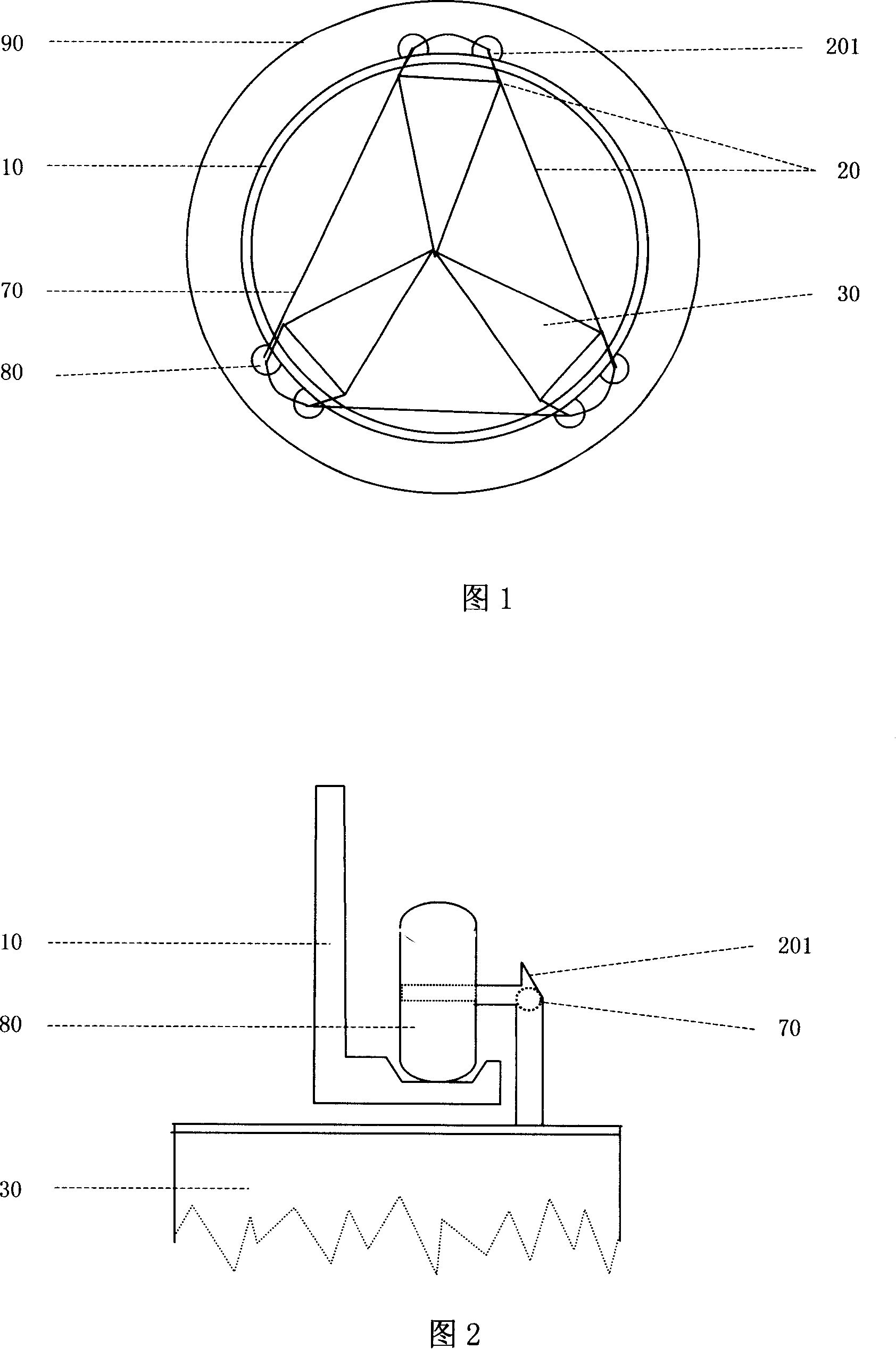
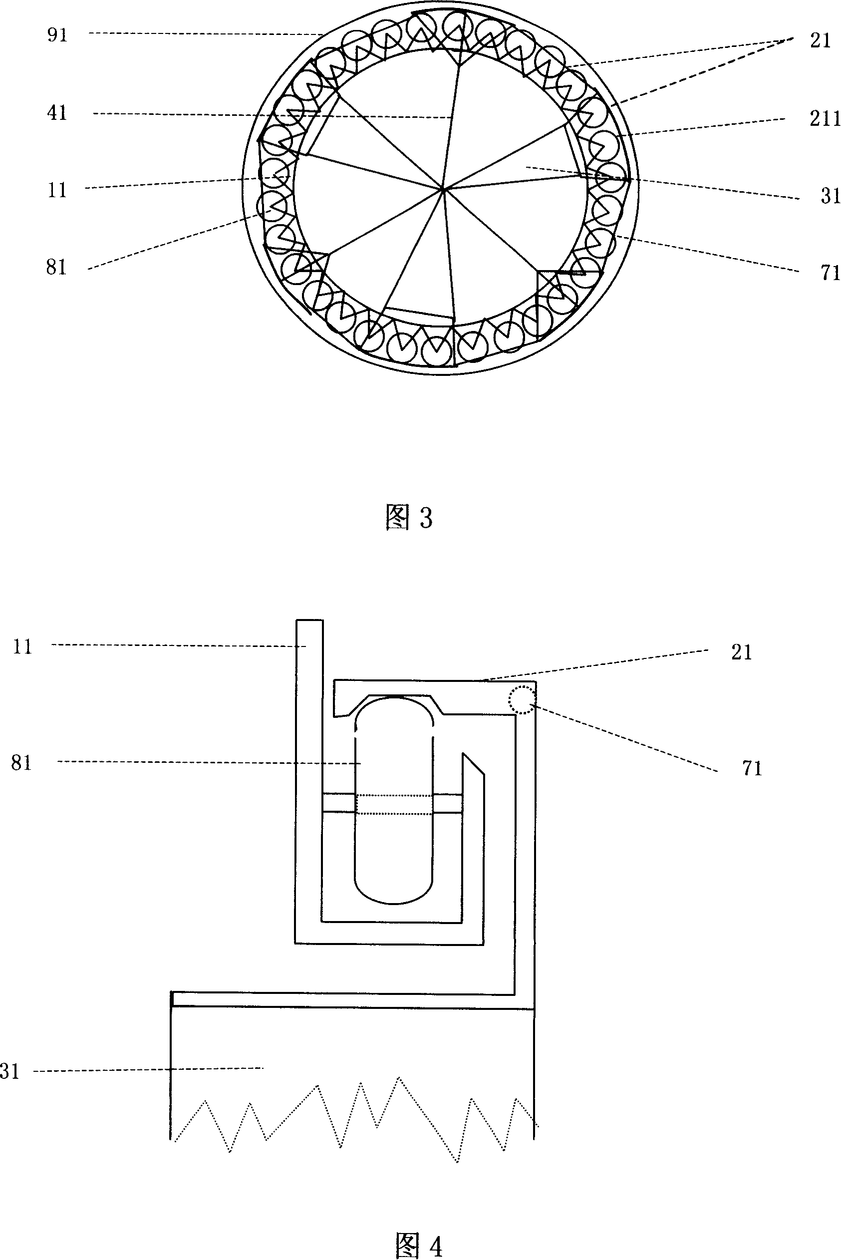
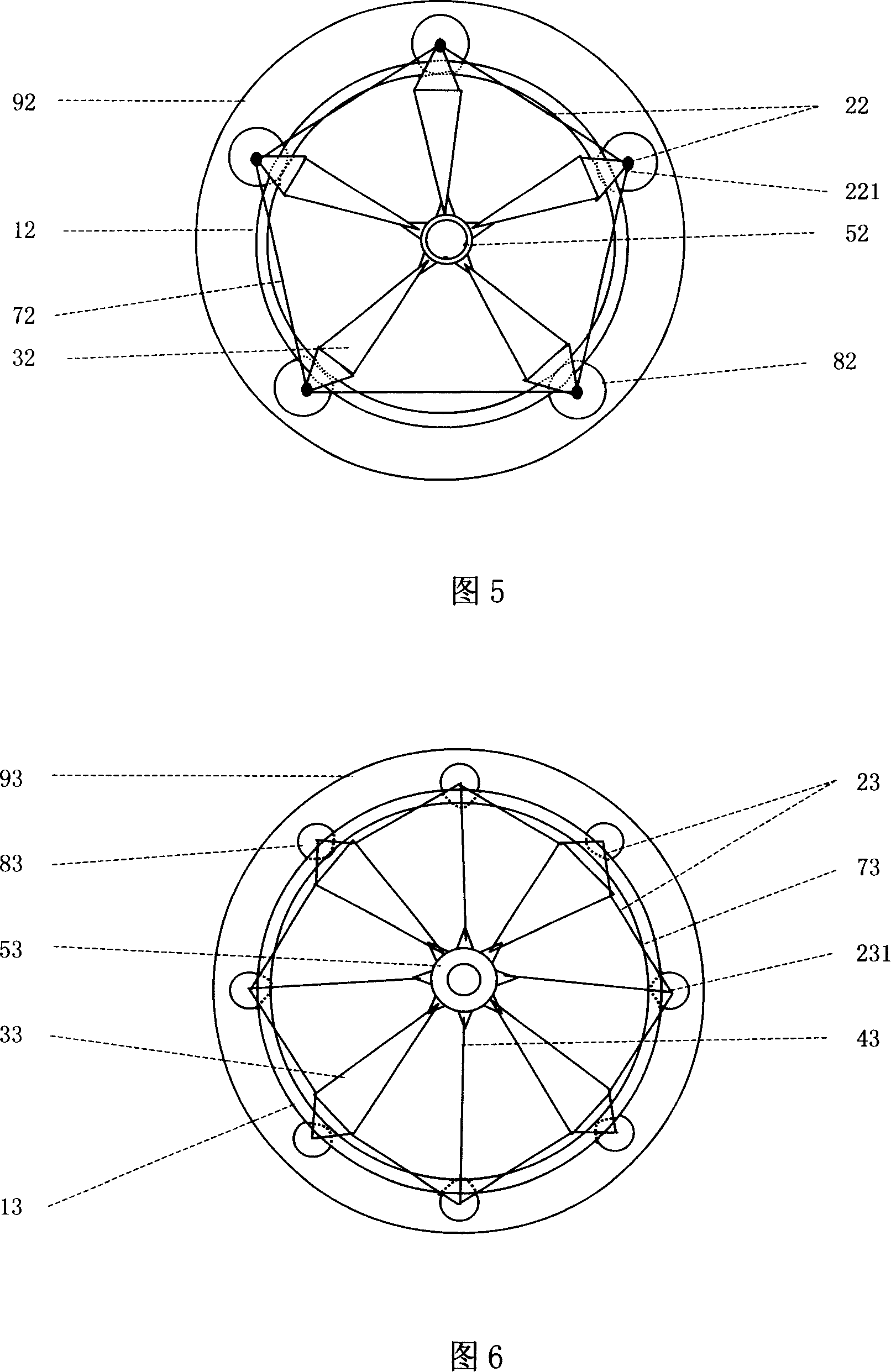
[0063] In this specification, the "circular slide rail" is generally a closed ring, which plays the role of providing support for the slider and the circular slide rail. It can also be fixed in a circular ring at a certain interval. The rollers, rollers, or other known technology rolling devices or friction reducing devices on the circular slide rails or brackets are used as circular slides. The outer side of the ring is the support surface of the slider and the slideway. The part of the slider connected to the fan blades can go around the side of the ring from the outside of the ring to connect with the fan blades on the inner side of the ring, and the other side of the ring The side of the ring is the connecting part of the circular slide rail air motor, the support frame and the support seat. In addition, the inside and part of the outside of the ring can also be used as the connecting parts of the ring-shaped slide rail wind motor, the support frame, and the support seat, and ...


PUM


Abstract

The annular slide rail wind motor for converting wind energy into mechanical energy has one annular slide rail for supporting, one annular sliding block comprising at least three sliding blocks connected with locating bars, and at least three wind blades connected with one connector in the circle center to drive the sliding blocks to slide circularly. The wind blades in the annular slide rail wind motor have light weight, small inertia and great wind force adaptability.

Description

Technical field [0001] The invention relates to a circular sliding rail wind motor which converts wind energy into mechanical energy. More specifically, it relates to a ring-shaped slider that is suspended on a circular slide rail and is formed by three or more slide blocks positioned in a ring shape. The supporting force of the circular slide rail is used to connect at one end. While three or more wind blades on the ring-shaped sliding block provide pulling force, they slide in a circular motion along the circular ring-shaped slide rail under the push of the wind blades. The other end of the wind blade is connected to other blades at the center of the circle, and each other obtains the pulling force from the opposite direction from the other blades. The two ends of the wind blade are straightened under the action of the pulling force in the opposite two directions, so that the wind blade is not needed. The support can perform the normal function of converting wind energy into mec...

Claims


Application Information

Patent Timeline
Patent Type & Authority Applications(China)
IPC IPC(8): F03D3/00F03D11/04F03D11/00F03D13/20F03D80/00
CPCY02E10/728Y02E10/74
Inventor 葛志仁
Owner 葛志仁
Features
  • Generate Ideas
  • Intellectual Property
  • Life Sciences
  • Materials
  • Tech Scout
  • Unparalleled Data Quality
  • Higher Quality Content
  • 60% Fewer Hallucinations
Learn More