Contact device for cone ring transmission
A technology of compression device and transmission, applied in the direction of transmission, friction transmission, transmission control, etc., can solve problems such as interruption of torque flow and damage
- Summary
- Abstract
- Description
- Claims
- Application Information
AI Technical Summary
Problems solved by technology
Method used
Image
Examples
Embodiment Construction
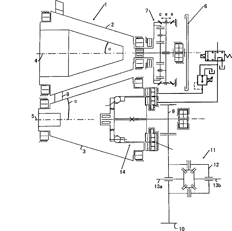
[0022] figure 1 A cone ring transmission is shown, which is generally designated 1 . The bevel ring transmission 1 has a first conical friction wheel 2 and a second conical friction wheel 3 . The conical friction wheels 2 , 3 are arranged opposite one another, with their axes of rotation extending parallel and spaced apart from one another. The axes of rotation of the conical friction wheels 2 , 3 are indicated by dashed lines 4 , 5 . Each conical friction wheel 2, 3 has an opening angle α.
[0023] In addition to the cone ring transmission 1, figure 1 Also shown is a clutch 6 of the motor vehicle which is not further shown here. A front transmission 7 is connected between the first conical friction wheel 2 and the clutch 6 . The front drive 7 in the form of a planetary gear train can switch between the two driving directions of the motor vehicle (forward, backward). In the engaged state, the clutch 6 transmits the torque of the driving device or the motor (not shown) to...
PUM
 Abstract
Description
Claims
Application Information
 - R&D
- Intellectual Property
- Life Sciences
- Materials
- Tech Scout
- Unparalleled Data Quality
- Higher Quality Content
- 60% Fewer Hallucinations
Browse by: Latest US Patents, China's latest patents, Technical Efficacy Thesaurus, Application Domain, Technology Topic, Popular Technical Reports.
© 2025 PatSnap. All rights reserved.Legal|Privacy policy|Modern Slavery Act Transparency Statement|Sitemap|About US| Contact US: help@patsnap.com


