Insulation inspecting apparatus

A technology of insulation inspection and equipment, applied in the direction of instruments, testing dielectric strength, measuring devices, etc., can solve problems such as insufficient methods

Inactive Publication Date: 2008-02-27
TOYOTA JIDOSHA KK +2
View PDF3 Cites 10 Cited by
  • Summary
  • Abstract
  • Description
  • Claims
  • Application Information

AI Technical Summary

Problems solved by technology

Although the above three documents disclose methods of identifying defect regions based on concepts different from th

Method used


Image

  • Insulation inspecting apparatus
  • Insulation inspecting apparatus
  • Insulation inspecting apparatus

Examples


Embodiment Construction

[0023] Embodiments of the insulation inspection apparatus according to the present invention will be described below. The same or corresponding elements have the same reference numerals, and descriptions thereof will not be repeated.

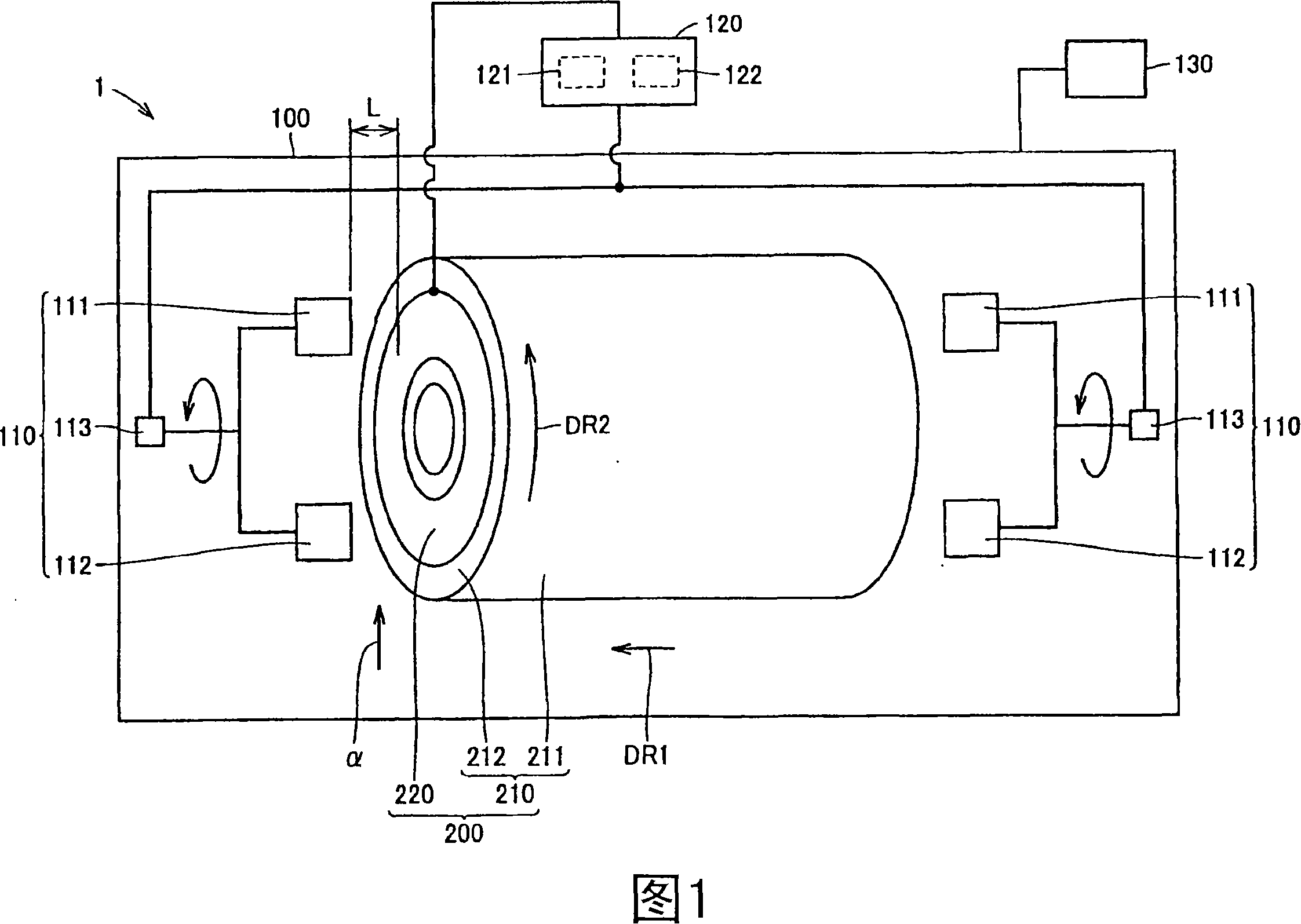
[0024] FIG. 1 shows the configuration of an insulation inspection device according to an embodiment of the present invention. Referring to FIG. 1 , the insulation inspection apparatus 1 of the present embodiment includes a chamber 100 (inspection container).

[0025] The stator 200 is placed in the chamber 100 . The stator 200 includes a stator core 210 and coil ends 220 .

[0026] Plates formed of a magnetic material such as iron, iron alloy, etc. are stacked to constitute the annular stator core 210 . A plurality of tooth portions (not shown) and groove portions (not shown) as recesses between the teeth are formed on the inner peripheral surface of the stator core 210 . The slot portion is formed to open on the inner peripheral side of the...


PUM


Abstract

The invention discloses an insulation inspection device (1) provided with a chamber (100) capable of accommodating a stator (200) with windings; electrodes (111, 112) capable of running along the coil ends ( 220) peripheral movement; a voltage applying unit (121), which is used to apply a voltage between the coil end (220) and the electrodes (111, 112); a detection unit (122), which detects the coil end (220) and a current and/or voltage between the electrodes (111, 112); and a pressure reducing unit (130), which reduces the pressure in the chamber (100).

Description

technical field [0001] The present invention relates to an insulation inspection device, in particular, to an insulation inspection device for detecting whether there is an insulation defect in a winding and its location by discharging at the region of the insulation defect of the winding. Background technique [0002] A method for detecting insulation defects at windings is conventionally known. [0003] For example, Japanese Patent Laid-Open No. 64-9360 discloses a method for detecting the presence and location of pinholes in windings by reducing the pressure in a container to cause partial discharge while applying constant pressure to the windings of a rotating electrical machine. [0004] Further, Japanese Patent Laid-Open No. 2003-248028 discloses a method for identifying the position of a coil defect by means of a liquid level sensor, which includes the steps of: gradually supplying a non-corrosive and conductive inspection liquid into the inspection box, at the electr...

Claims


Application Information

Patent Timeline
IPC IPC(8): G01R31/12G01R31/16G01R31/06
CPCG01R31/346
Inventor 相原浩藤木淳清原进
Owner TOYOTA JIDOSHA KK
Why Eureka
Try Eureka