Sander

A grinding machine and main body technology, which is applied in the direction of grinding frame, grinding machine, grinding machine parts, etc., can solve the problems of no dust cover, dust entry, restricted shape, etc., and achieve cost increase and high dust resistance Effect

Inactive Publication Date: 2008-03-05
MAKITA CORP
View PDF1 Cites 13 Cited by
  • Summary
  • Abstract
  • Description
  • Claims
  • Application Information

AI Technical Summary

Problems solved by technology

[0004] However, since the above-mentioned dust cover is a light and thin flexible material with little rigidity, it is necessary to install its upper and lower ends on the opposite surfaces of the main body and the base with screws, etc., and when there are gaps in each installation part, dust may will enter through these gaps
Therefore, in order to maintain the airtightness of the mounting portion, it is necessary to ensure the flatness of the mounting surfaces on the main body and the base, thereby limiting the shape of the main body or the base

Method used


Image

  • Sander
  • Sander

Examples


Embodiment approach 1

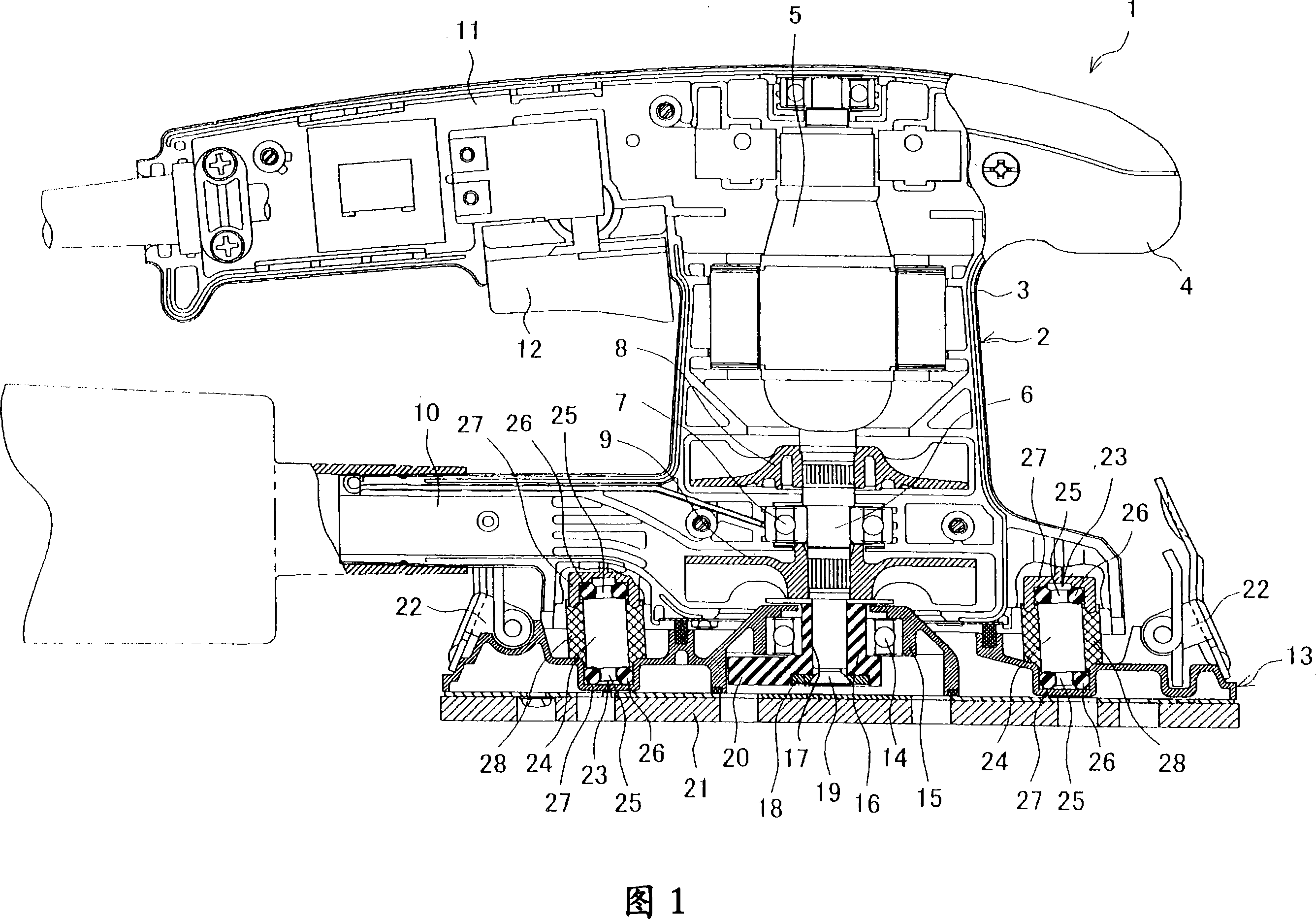
[0013] FIG. 1 is a vertical cross-sectional view of a finishing grinder as an example of grinders. The finishing grinder 1 has a main body 2 and a base 13 located therebelow. The main body 2 is formed by longitudinal two-piece covers 3 and 4, and accommodates a motor 5 facing downward. An output shaft 6 rotatably supported by a ball bearing 7 projects downward of the main body 2. A fan 8 for cooling the motor 5 is fixed to the output shaft 6 at a position above the ball bearing 7 so that the fan plane is perpendicular to the output shaft 6 . At the lower position of the ball bearing 7, the dust collection fan 9 is fixed on the output shaft 6 in a state where the fan plane is perpendicular to the output shaft 6. The dust collection fan 9 sucks dust from the bottom of the main body 2 and sends it to the main body 2 side dust collection nozzles 10. Reference numeral 11 denotes a handle extending from the upper part of the main body 2, and reference numeral 12 denotes a trigger. ...

Embodiment approach 2

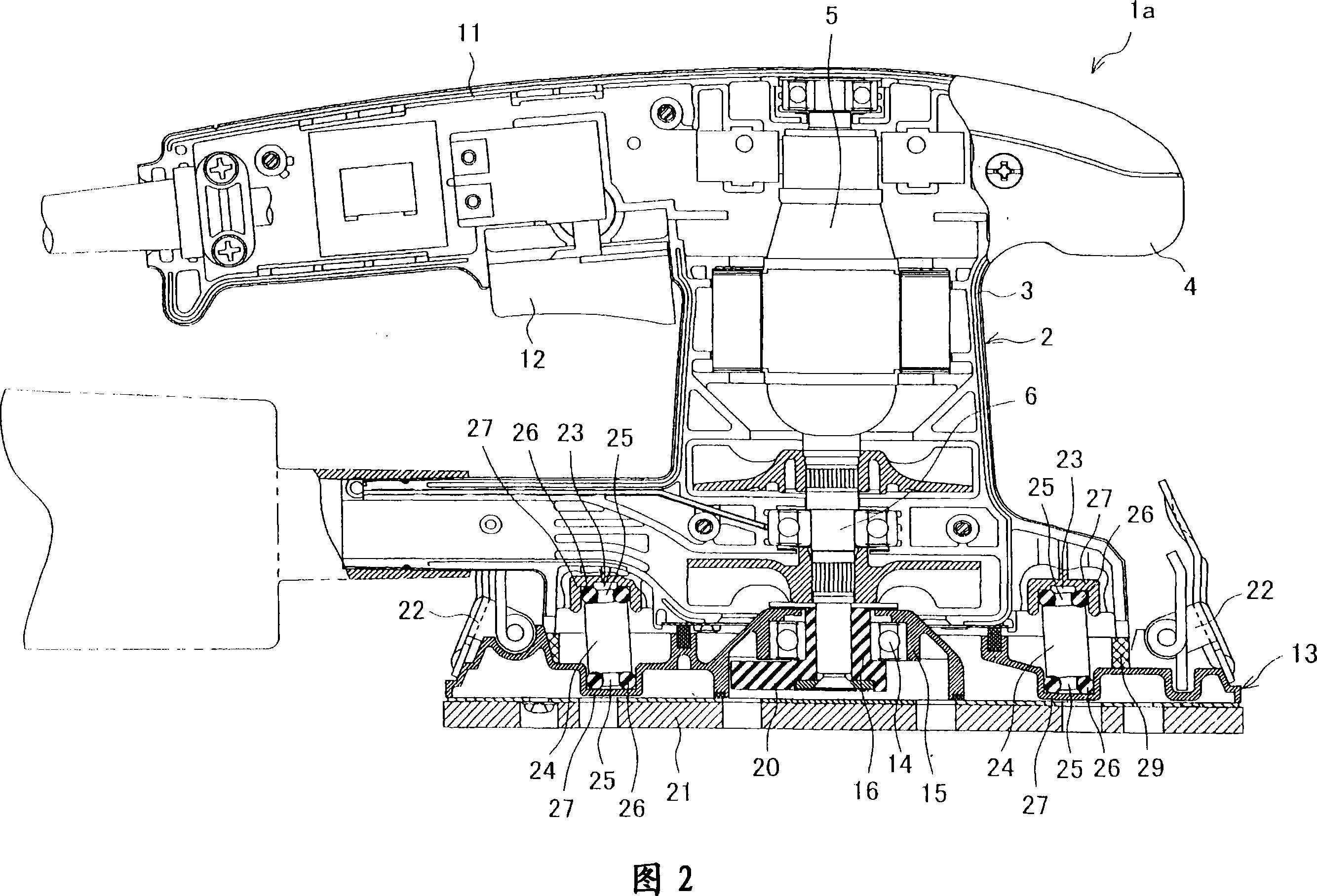
[0024] Next, other embodiments of the present invention will be described. Components having the same configuration as those in Embodiment 1 are denoted by the same reference numerals, and repeated explanations are omitted.

[0025] In the finishing sander 1a shown in FIG. 2 , the sponge sleeve 29 is not mounted on each leg 23 but stuck between the main body 2 and the base 13 and surrounds the entire area where the legs 23 , 23 are provided. That is, the sponge sleeve 29 is formed as a cylindrical body along the outer shape of the lower part of the main body 2, and is slightly longer than the vertical distance between the main body 2 and the base 13 in the axial direction, and its upper end is in pressure contact with the lower part of the main body 2. The upper and lower ends of the surface are in pressure contact with the upper surface of the base 13 at positions inside the clamping member 22 and are in close contact, thereby sealing the entire area where the legs 23 are pro...


PUM


Abstract

The present invention provides a grinding machine, which ensures the feet have high dustproof quality by simple structure. Sponge bushing (28) is installed on the peripheral part of the foot main body (24) of each foot of the finish machining grinding machine (1). The sponge bushing (28) is a tube type body with longer length than the distance in up and down direction of the upper-lower pillow (27) in axial direction, the upper and lower end of the sponge bushing contact the hatch end of the pillow (27) separately, and close the pillow (27) through distortion according to the shape of the hatch edge. Thus, dust can not enter the inner of the pillow (27) between the feet main body (24) and the pillow (27).

Description

technical field [0001] The invention relates to a sander in which, beneath a body with a motor, there is a base driven by rotation of the motor in orbital motion. Background technique [0002] In the grinder, the output shaft is protruded below the main body having the motor, and the base is eccentrically connected to the output shaft, whereby the output shaft rotates as the motor is driven, thereby causing the base to perform orbital motion (eccentric circular motion) , the material to be ground can be ground with sandpaper laid on the bottom surface of the base. In order to control the rotation of the base and prevent the vibration (especially up and down shaking) accompanying the orbital movement, the main body and the base are respectively provided with recessed pedestals relative to the main body and the base, the pedestal and the base on the main body The pedestals on the base are arranged facing each other, and supporting feet are erected between the pedestals. Most...

Claims


Application Information

Patent Timeline
Patent Type & Authority Applications(China)
IPC IPC(8): B24B41/02B24B47/04
CPCB24B23/04B24B55/055
Inventor 萩原浩一野尻裕士
Owner MAKITA CORP
Why Eureka
Try Eureka