Blowing and sucking machine

A technology of blower and main machine, applied in vacuum cleaners, vacuum cleaner equipment, applications, etc., can solve the problems of inconvenient operation and bulky blower, and achieve the effect of simple operation

Active Publication Date: 2008-03-05
POSITEC POWER TOOLS (SUZHOU) CO LTD
View PDF6 Cites 30 Cited by
  • Summary
  • Abstract
  • Description
  • Claims
  • Application Information

AI Technical Summary

Problems solved by technology

The two different working modes of the blowing machine require two different pipe passages for the blowpipe and the suction pipe to perform the work. In the wo

Method used


Image

  • Blowing and sucking machine
  • Blowing and sucking machine
  • Blowing and sucking machine

Examples


Embodiment approach

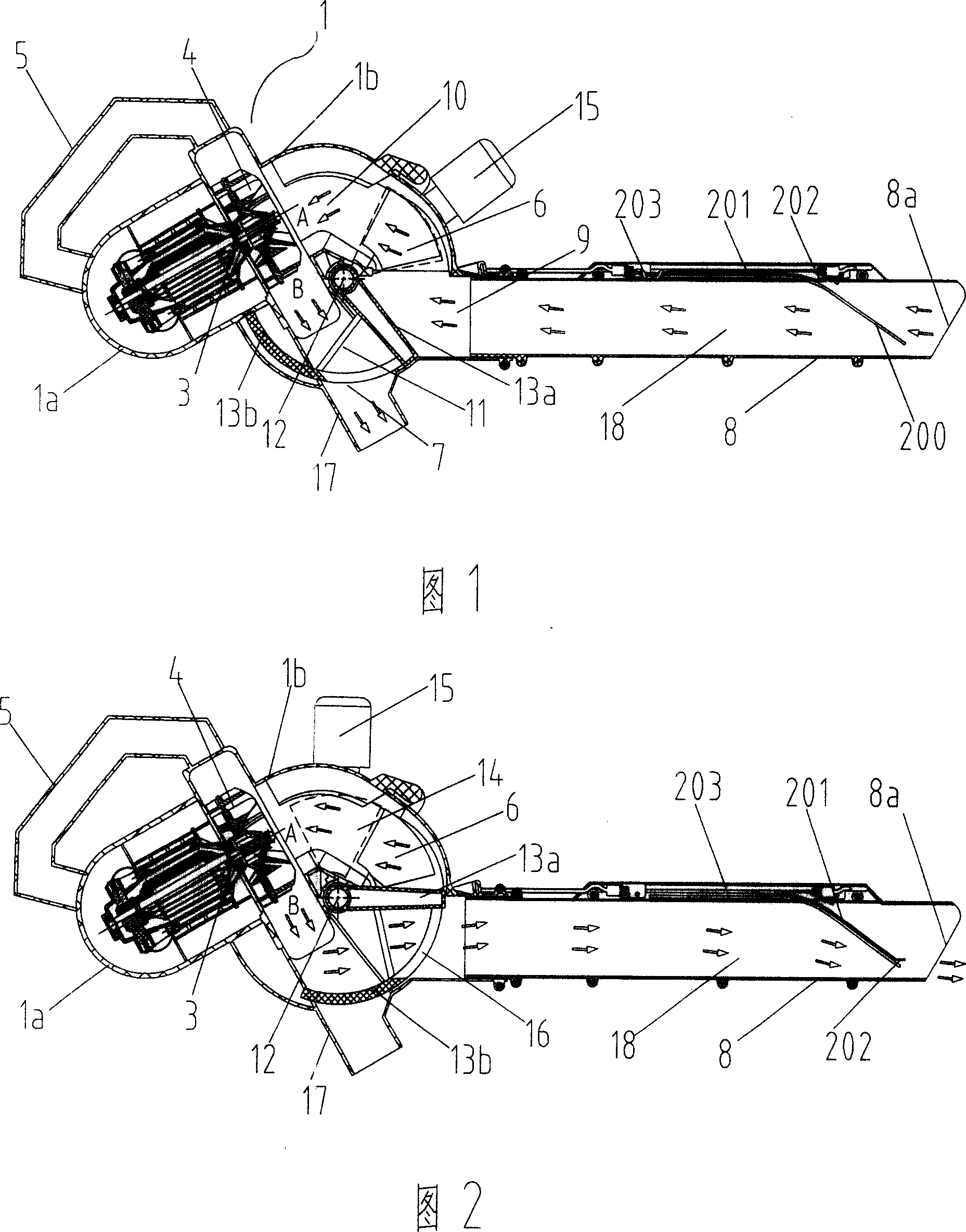
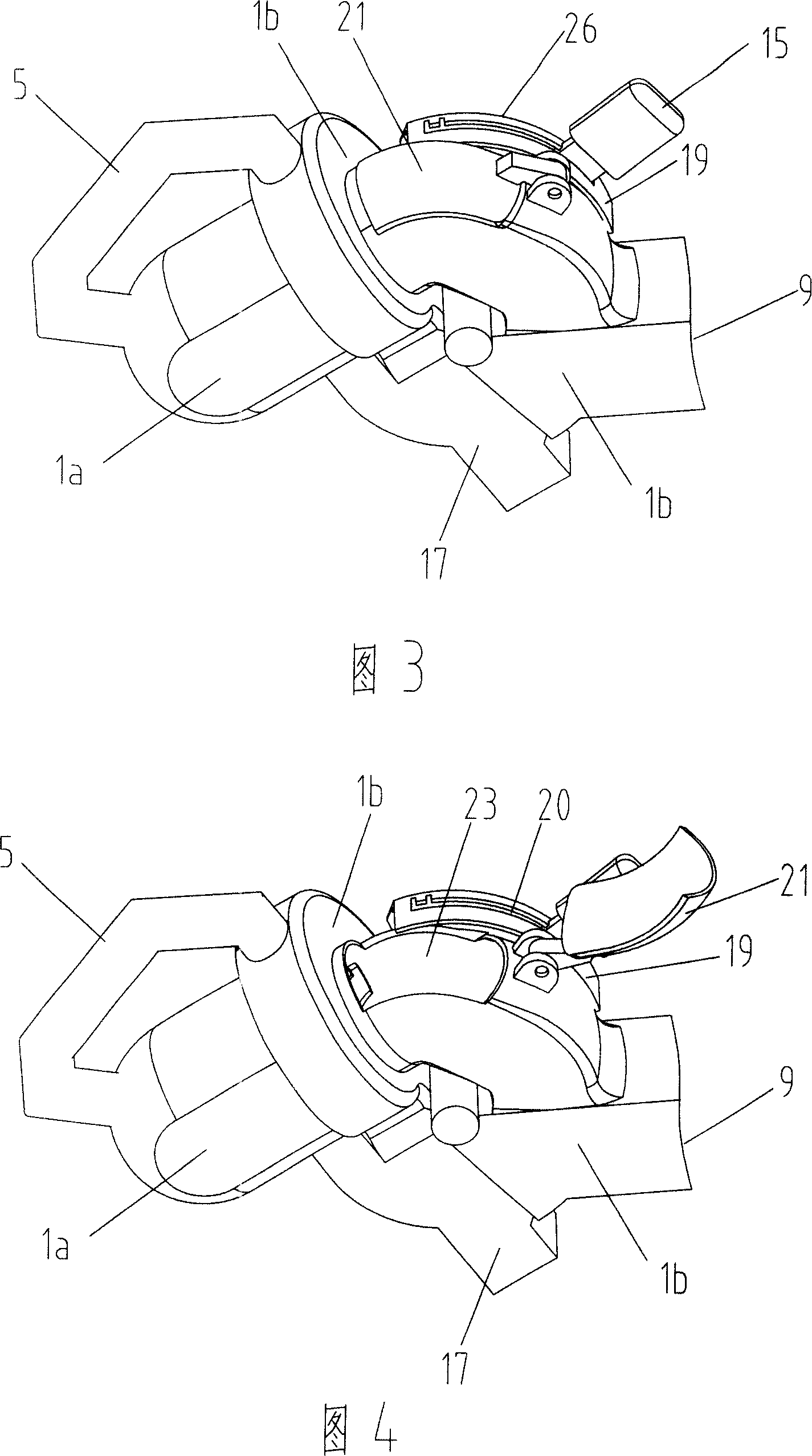
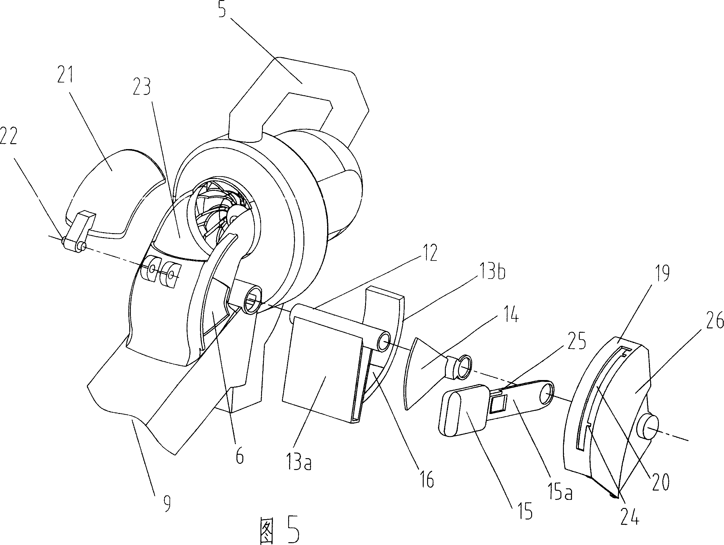
[0061] Referring to Fig. 6, it is a second embodiment of the present invention, which has a similar structure to the above-mentioned first example, and the main casing 27 includes a casing 27a accommodating the motor 2' and a casing accommodating the fan 4' body 27b, the upper part of the housing 27b is provided with an air inlet 30, and the lower part of the housing 27b is correspondingly provided with a dust outlet 31, and a dust outlet pipe is detachably connected to the housing corresponding to the dust outlet 31 32. The dust outlet pipe 32 can be provided with a collection bag for dust collection, and the conversion mechanism 33 is provided in the cavity 10' formed by the casing 27b, and is used for switching between two different working positions of dust blowing and dust suction The housing 27b is also provided with a single-cavity port 9, and one end of the suction pipe 8' is releasably docked with the single-cavity port 9', and the other end of the suction pipe 8' is p...


PUM


Abstract

The blowing and sucking machine as gardening apparatus consists of one casing, one motor, one motor rotated fan, and one blowing/sucking function converting mechanism. The casing has one air inlet and one dust outlet; and the blowing/sucking function converting mechanism has one controller for controlling the mode conversion between blowing mode and the sucking mode. The casing is also provided with one single cavity port to communicate optionally to the air inlet or the dust outlet, so that the blowing and sucking machine can operate in a blowing mode or a sucking mode separately.

Description

technical field [0001] The invention relates to an outdoor gardening electric tool, in particular to a leaf blower. Background technique [0002] In traditional blowing and suction machines, a blowpipe and a suction pipe are generally installed on the main body of the blowing and suction machine. The blowpipe and the suction pipe are respectively responsible for two different functions of blowing and suction. The diameter of the blowpipe is relatively large, and the diameter of the blowpipe is relatively small, and the diameter of the blowpipe has a process of gradually decreasing in the direction of its longitudinal extension. The blowpipe and the suction pipe are usually arranged in parallel and integrated. Inhale to switch between two different working modes. When the blower is in the blowing mode, the high-speed airflow blown from the blowing pipe will blow and gather the leaves scattered on the ground. At this time, the blower can be used as a dust blower; when the blo...

Claims


Application Information

Patent Timeline
IPC IPC(8): E01H1/08A47L5/12
CPCY02B40/82A01G20/47
Inventor 王其彬马卫民
Owner POSITEC POWER TOOLS (SUZHOU) CO LTD
Why Eureka
Try Eureka