Axial turbine

An axial-flow turbine and stage technology, which is applied in mechanical equipment, non-variable-capacity pumps, engine components, etc., can solve the problems of disrupting the mainstream of steam and reducing the output of the stage, so as to prevent the decline of the stage output and improve the turbine stage. The effect of class efficiency

Inactive Publication Date: 2008-03-05
HITACHI LTD
View PDF1 Cites 13 Cited by
  • Summary
  • Abstract
  • Description
  • Claims
  • Application Information

AI Technical Summary

Problems solved by technology

However, as will be described in detail later, the blown flow interferes with the flow (steam main flow) flowing down through the stator blades and disturbs the steam main flow, resulting in a decrease in the stage output.

Method used


Image

  • Axial turbine
  • Axial turbine
  • Axial turbine

Examples


Embodiment Construction

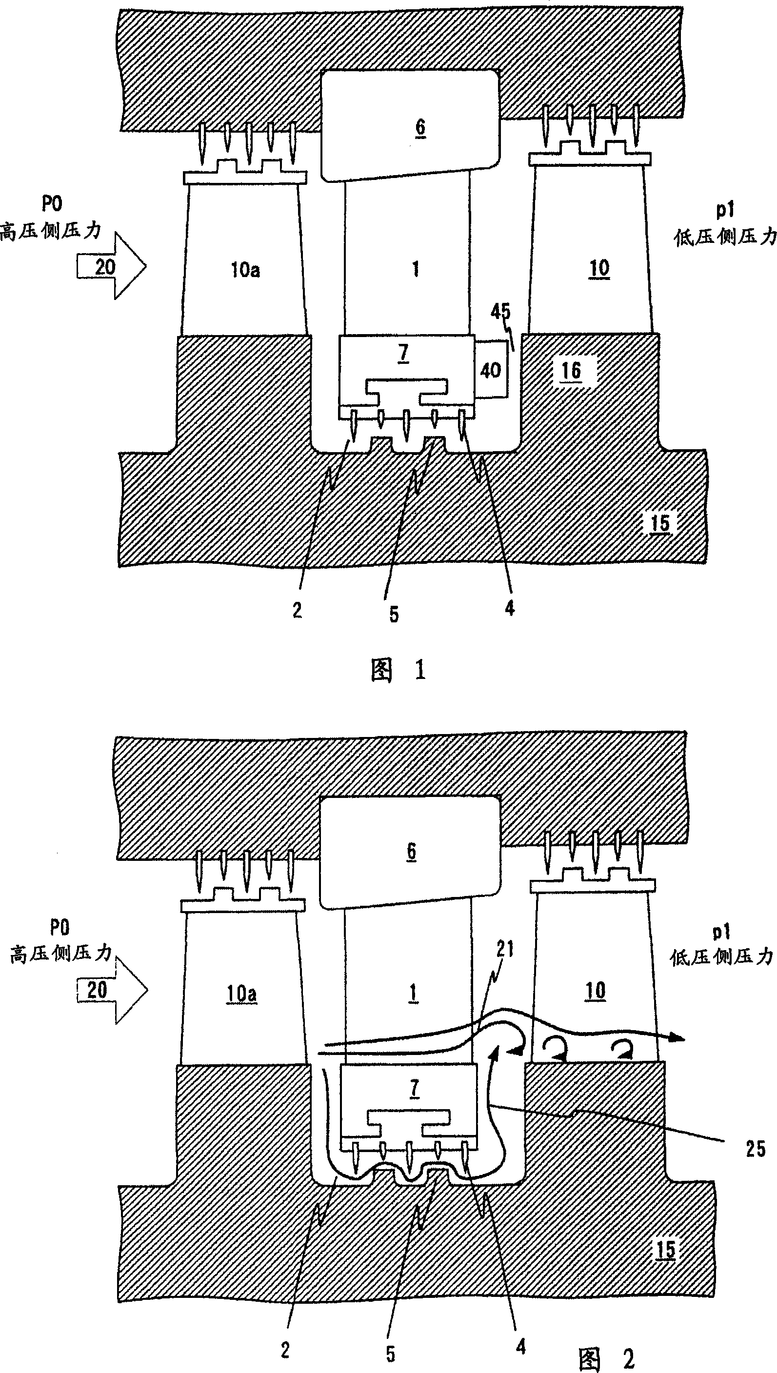
[0020] One embodiment of the axial turbine stage of the present invention will be described with reference to the drawings.

[0021] Figure 1 shows a cross-sectional view of a turbine stage of the invention. As shown in Fig. 1, the turbine stage is arranged between the high-pressure part P0 and the low-pressure part P1, and consists of the stator blades 1 fixed on the outer peripheral side diaphragm 6 and the inner peripheral side diaphragm 7 and the rotating rotor 15. The moving blade 10 constitutes. In the case of a turbine having a multi-stage turbine stage, the rotor blades 10a of other stages are provided on the upstream side of the stator blades 1 .

[0022] The flow (steam main flow) 20 is caused by the pressure difference P0-P1, and the flow 20 is accelerated by the stator blade 1 and is deflected in the circumferential direction. The flow having a velocity component in the circumferential direction through the stator blade 1 imparts kinetic energy to the rotor blade...


PUM


Abstract

An axial turbine has a turbine stage including stator blades fixedly provided on a stationary section and moving blades fixedly provided on a rotating section and has a structure in which a flow blowing out from a space formed between the stator blades and the moving blades exists. In order to prevent a decrease in stage output power due to such blowout flow thereby to improve the turbine stage efficiency, the axial turbine comprises a member coupling an inner circumferential side of the stator blades, and a structure provided on a surface of the member opposed to the moving blades for bending a flow blowing out from the side of the rotating section into a space between the stator blades and the moving blades in a rotational direction of the rotating section.

Description

technical field [0001] The present invention relates to axial flow turbines, in particular to drum rotor axial flow turbines. Background technique [0002] Axial-flow turbines such as steam turbines and gas turbines have a turbine stage composed of fixed blades that convert fluid pressure into kinetic energy, and moving blades that convert fluid pressure or kinetic energy into rotational force of a rotating part. The fixed blades are fixed on the outer peripheral side partition plate and the inner peripheral side partition plate as the stationary part. The rotor blades are provided on a rotor that is a rotating portion. A gap is provided between the inner peripheral side separator and the rotor, and a seal is provided in the gap. The seal is utilized to reduce leakage flow through the gap. However, in order to obtain stable rotation of the rotor, the gap cannot be reduced beyond a certain level, so that the leakage flow through the gap cannot be completely zeroed. [000...

Claims


Application Information

Patent Timeline
Patent Type & Authority Applications(China)
IPC IPC(8): F01D9/00
CPCF01D5/143F01D5/145F01D11/02F05B2240/571F05D2240/56F01D11/001F05D2240/126F05D2240/129F04D29/32F04D29/38
Inventor 妹尾茂树
Owner HITACHI LTD
Why Eureka
Try Eureka